Do you have a question about the Clevo NL41CU and is the answer not in the manual?
Introduces the manual's scope for servicing/upgrading NL40CU/NL41CU notebooks, referencing the User's Manual.
Details CPU options, Memory, LCD, Storage, Video Adapter, Keyboard, Audio, Security, and Connectivity.
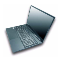
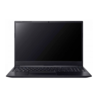
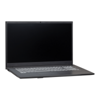
Identifies key external components like PC Camera, Ports, Vents, Keyboard, and Touchpad across multiple views.
Illustrates key parts and connectors on the top and bottom sides of the mainboard.
Provides step-by-step instructions for disassembling notebook parts and subsystems.
Covers safety guidelines during disassembly, including static discharge, corrosion, and environmental care.
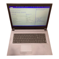
Guides for removing Battery, System Memory (RAM), Wireless LAN, M.2 SSD, and CCD.
Table indicates where to find illustrations for Top, Bottom, LCD, and MB part lists.
Provides part numbers for Top, Bottom, LCD, and MB assemblies.
Shows the overall system architecture and interconnections of major components.
Detailed schematics for processor interfaces, signals, and DDR4 memory slots.
Schematics for HDMI, Panel, USB/DP MUX, Type-C, and ASM1543 connectors.
Illustrates various power rails (3V, 5V, 1.8V, VCore) and PD functions.
Schematics for LAN controller, I/O boards, and Power Button board.
| LAN | Gigabit Ethernet |
|---|---|
| Keyboard | Backlit Keyboard |
| Card Reader | Micro SD Card Reader |
| Display | 14" (35.56cm) FHD (1920x1080) LED Backlit Anti-Glare Display |
| RAM | Up to 64GB DDR4 |
| Graphics | Intel Iris Xe Graphics |
| Operating System | Windows 10 Pro |
| Wireless | Wi-Fi 6, Bluetooth 5.1 |
| Webcam | HD Webcam |
| Ports | HDMI |
| Battery | 36WH |
| Processor | Intel Core i7-1165G7 |