Do you have a question about the Clevo NJ70CU and is the answer not in the manual?
Company reserves the right to revise, information is for reference only, no liability for errors.
Lists registered trademarks like Intel, Microsoft, and others.
Intended for service personnel, covers servicing/upgrading NJ70CU notebook PC.
Basic precautions to reduce risk of fire, electric shock, and injury, and FCC compliance statement.
Suggestions to prevent damage to the notebook computer, like avoiding drops, shock, and overheating.
Computer has specific power requirements, use approved adapter, check compatibility.
Precautions for using, recharging, and disposing of batteries to prevent explosion or damage.
Suggests consulting the User's Manual and provides step-by-step instructions for initial setup.
Manual covers servicing/upgrading the NJ70CU notebook PC, refers to User's Manual for OS/drivers.
Lists detailed specifications for CPU, BIOS, Memory, LCD, Storage, Video Adapter, Keyboard, Audio, Security, M.2 Slots, Card Reader.
Details computer ports, communication modules, AC adapter, and battery specifications.
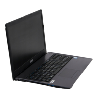
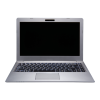
Identifies external components on the top view of the laptop, including camera, microphone, LCD, keyboard.
Identifies external components on the front and right side views, including LED indicators, card reader, and USB ports.
Identifies external components on the left side and rear views, including DC-in jack, LAN, monitor port, USB, vent, and battery.
Identifies external components on the bottom view, including battery, vents, and speakers.
Provides a visual guide to the key components on the top side of the mainboard.
Provides a visual guide to the key components on the bottom side of the mainboard.
Identifies various connectors located on the top side of the mainboard.
Identifies various connectors located on the bottom side of the mainboard.
Explains chapter purpose, disassembly process, margin boxes, and lists recommended maintenance tools.
Describes four types of connectors and how to release/separate them.
Safety and handling precautions to avoid personal injury and computer damage during maintenance.
Lists disassembly steps for various components and provides corresponding page references.
Step-by-step instructions with diagrams for safely removing and installing the battery.
Instructions for removing and replacing the 2.5" SATA hard disk drive.
Continues instructions for removing the HDD assembly, including screws and bracket.
Step-by-step guide for removing and upgrading the computer's RAM modules.
Continues instructions for RAM module removal, insertion, and securing.
Instructions for safely removing the keyboard, including disconnecting the ribbon cable.
Step-by-step process for removing and replacing the optical drive and its bezel.
Instructions for removing the WLAN module, including disconnecting cables and screws.
Table detailing cable types (color, antenna) for WLAN and LTE modules.
Instructions for removing the 4G module, including cable disconnection and screw removal.
Step-by-step guide for removing the M.2 SSD module, including screw removal and thermal pad placement.
Instructions for removing the CCD, involving handling the LCD panel and front cover.
Continues instructions for CCD removal, including cable disconnection and module extraction.
Table indicating where to find specific part list illustrations for different notebook components.
Lists part numbers and descriptions for components located on the top of the laptop.
Lists part numbers and descriptions for components located on the bottom of the laptop.
Lists part numbers and descriptions for components related to the LCD panel.
Lists part numbers and descriptions for the dummy optical drive bay.
Lists part numbers and descriptions for the SATA DVD writer and its bezel.
Lists part numbers and descriptions for the second HDD bracket, module, and bezel.
Lists part numbers for various components on the mainboard (MB), including connectors and cables.
Provides a high-level block diagram of the notebook's system architecture and component interconnections.
Detailed schematics showing processor pin assignments, configuration, and signal connections.
Schematics detailing the pin assignments and connections for DDR4 SO-DIMM slots A and B.
Schematic for the LCD panel connector and inverter circuitry for backlight control.
Schematics for display controller (RTD2168), PD function, HDMI, and HDD/ODD/LED/TPM.
Schematics for USB Type-C, M.2 SSD, Audio Codec, and I/O connectors.
Schematics for various voltage rails like VDD3/VDD5, 3V/5V, 1.05VA, 1.8V/2.5V, and controllers.
Schematics for the smart charger, DC input, lid switch, click board, audio board, and power switch board.
Schematics for RGB keyboard lighting control and power sequence diagrams.
| Category | Laptop |
|---|---|
| Manufacturer | Clevo |
| Model | NJ70CU |
| Display Size | 17.3 inches |
| Memory Type | DDR4 |
| Weight | 2.5 kg |
| Display | 1920x1080 |
| RAM | 16GB |
| Storage | 512GB SSD |
| Operating System | Windows 11 |
| Ports | HDMI, RJ-45, Audio Jack |
| Battery | 4-cell |