Residential H&V - 60Hz HFC-410A:
Rev:January 30, 2017
12
Geothermal Heating and Cooling
Vertical Installation
Return
Air Inlet
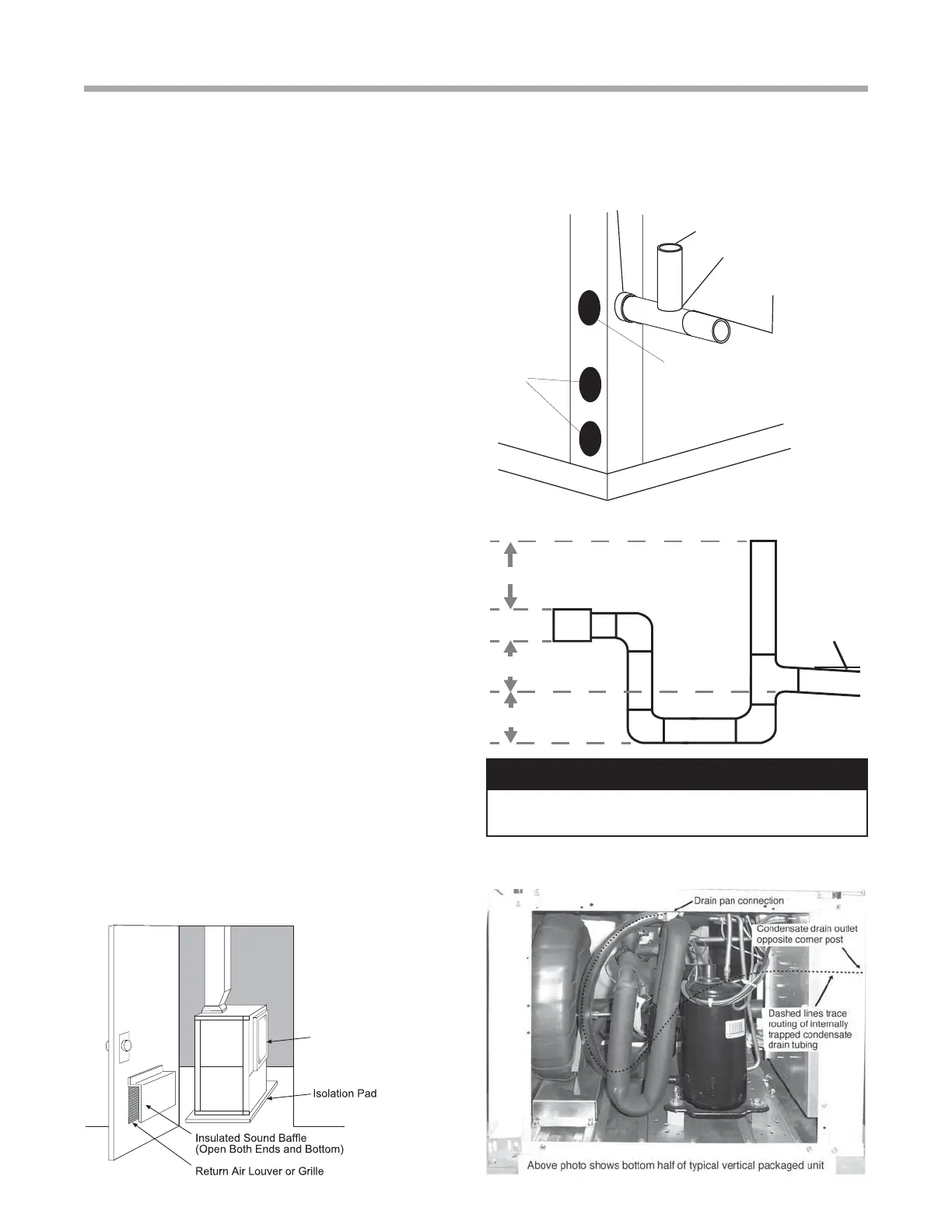
Figure 9: Vertical Sound Attenuation
Vent
*3/4" FPT
3/4" PVC
Alternate
Condensate
Location
Water
Connections
1/8" per foot
slope to drain
Figure 10a: Vertical Unit with Internal Condensate Trap
Figure 10c: Vertical Internal Condensate Trap
Condensate Piping for Vertical Units - Some units utilize
a condensate hose inside the cabinet as a trapping loop;
therefore an external trap is not necessary, other units require
an external condensate trap. Observe the condensate drain
connection to determine if a fi eld provided trap is necessary.
Units with a PVC socket connection are internally trapped,
units with stainless steel MPT connection require an external
trap. Figures 10a and b show typical condensate connections.
Figure 10c illustrates the internal trap that is present in some
units. Each unit must be installed with its own individual trap
and connection to the condensate line (main) or riser. Provide
a means to fl ush or blow out the condensate line. DO NOT
install units with a common trap and/or vent.
Always vent the condensate line when dirt or air can collect
in the line or a long horizontal drain line is required. Also vent
when large units are working against higher external static
pressure than other units connected to the same condensate
main since this may cause poor drainage for all units on the
line. WHEN A VENT IS INSTALLED IN THE DRAIN LINE, IT
MUST BE LOCATED AFTER THE TRAP IN THE DIRECTION
OF THE CONDENSATE FLOW.
Install the external condensate trap with the top of the trap
positioned below the unit condensate drain connection as
shown in fi gure 10b. Design the depth of the trap (water-seal)
based upon the amount of the ESP capability of the blower
(ex. 2 inches (51mm) of ESP capability requires 2 inches
(51mm) of trap depth). As a general rule, 1-1/2 inch (38mm)
trap depth is the minimum.
Sound Attenuation for Vertical Units - Sound attenuation
is achieved by enclosing the unit within a small mechanical
room or a closet. Additional measures for sound control
include the following:
1. Mount the unit so that the return air inlet is 90° to the
return air grille. Refer to Figure 9. Install a sound baffl e
as illustrated to reduce line-of sight sound transmitted
through return air grilles.
2.
Mount the unit on a Tranquility Unit Isolation Pad to
minimize vibration transmission to the building structure.
For more information on Tranquility Unit Isolation Pads,
contact your distributor.
Figure 10b: Vertical Unit with External Condensate Trap
CAUTION!
CAUTION! Ensure condensate line is pitched toward drain
1/8 inch per ft [11mm per m] of run.



 To Next Page