EasyManua.ls Logo

CLIMAVENETA CVM 2 User Manual

CLIMAVENETA CVM 2
23 pages
To Next Page IconTo Next Page
Page #1 background imageLoading...
Page #1 background image
TECHNICAL MANUAL
CVM 2
C 5001 CV/04-99 GB
1
Summary
1 CONNECTIONS ..............................................................................................................................4
1.1 TEMPERATURE PROBES.............................................................................................................4
1.2 PRESSURE PROBES.......................................................................................................................5
1.3 LIVE DIGITAL INPUTS................................................................................................................6
1.4 RELAY OUTPUTS .......................................................................................................................6
1.5 SERIAL CONNECTIONS ..............................................................................................................7
1.6 KEYBOARD...................................................................................................................................7
1.7 REMOTE KEYBOARD..................................................................................................................7
1.8 POWER SUPPLY...........................................................................................................................8
2 SETUP................................................................................................................................................8
2.1 ACCESS TO PROGRAMMING.......................................................................................................8
3 SOFTWARE.....................................................................................................................................9
3.1 DESCRIPTION OF USER INTERFACE ......................................................................................... 9
3.2 UNIT STARTUP............................................................................................................................9
3.3 UNIT SHUTDOWN.....................................................................................................................10
3.4 ALARMS...................................................................................................................................10
3.4.1 Circuit and/or compressor alarms..............................................................................10
3.4.2 General alarms...............................................................................................................10
4 ALARM SIGNALS ........................................................................................................................11
5 HOW TO VISUALISE THE RESOURCE STATUS .................................................................13
5.1 VISUALISATION OF UNIT'S RESOURCE STATUS....................................................................13
6 REGULATION................................................................................................................................15
6.1 CHILLED WATER REGULATION .............................................................................................15
6.2 HOT WATER REGULATION .....................................................................................................15
7 PARAMETER LIST.......................................................................................................................16
8 ENCLOSURES ...............................................................................................................................23
Question and Answer IconNeed help?

Do you have a question about the CLIMAVENETA CVM 2 and is the answer not in the manual?

CLIMAVENETA CVM 2 Specifications

General IconGeneral
Cooling CapacityNot available
Heating CapacityNot available
Power SupplyNot available
RefrigerantNot available
Sound Power LevelNot available
WeightNot available
DimensionsNot available

Summary

1 Connections

1.1 Temperature probes

Details the types of temperature probes, terminal connections, and resistance values at different temperatures.

1.2 Pressure probes

Describes the 4-20mA pressure probes, their terminal assignments, and corresponding pressure/current values.

1.3 Live digital inputs

Explains the logic meaning and terminal arrangement for AT digital inputs (230 Vac).

1.4 Relay outputs

Lists relay outputs with their N.O., N.C., and COM terminal connections for various unit functions.

1.5 Serial connections

Specifies the 8-pin, TTL telephone-type connector used for serial communication.

1.6 Keyboard

Details the connection diagram for the unit's keyboard to the main board terminals.

1.7 Remote keyboard

Provides the connection diagram for a remote keyboard kit, including power and signal lines.

1.8 Power supply

States that the unit receives a 230 Vac supply via terminals 49 and 50 (phase and neutral).

2 Setup

2.1 Access to programming

Step-by-step guide on how to access and navigate the unit's programming menu using keys and LEDs.

3 Software

3.1 Description of user interface

Explains the function of the POWER LED and how the electronic control is supplied with power.

3.2 Unit startup

Procedure for starting up the unit, including pressing ON/OFF/RESET and MODE keys for CHILLER/HEAT PUMP.

3.3 Unit shutdown

Instructions for shutting down the unit by pressing the ON/OFF/RESET key, causing the display to go off.

3.4 ALARMS

Details circuit/compressor and general alarms, including visualization on DISPLAY and ALARM LED, and reset procedures.

4 Alarm signals

5 How to visualise the resource status

5.1 Visualisation of the unit's resource status

Explains how to use the STATUS key and arrow keys to view various unit resource statuses and their meanings.

6 Regulation

6.1 Chilled water regulation

Details how to modify the working set point and differential for chilled water regulation via parameter 2.

6.2 Hot water regulation

Explains how to adjust the set point and differential for hot water regulation via parameter 3 in Heat Pump mode.

7 Parameter list

Unit Type and Set Points

Lists unit type, cooling/heating set points, and differential parameters (parameters 1-5).

Fan and Compressor Control Parameters

Details fan speed settings, modulating output limits, and compressor restart/safety times (parameters 6-19).

Defrost and Ventilation Settings

Configuration parameters for defrost start/end pressure, standby/max time, and forced ventilation (parameters 20-25).

Antifreeze and Pump Configuration

Settings for antifreeze control, fan motor phase, water pump operation, and alarm reset types (parameters 26-50).

Circuit Configuration and Set Points

Parameters for low pressure bypass, circuit configuration, antifreeze limits, and mode key settings (parameters 51-68).

Probe Configuration and Alarm Resets

Includes probe configuration, offsets, defrost cycles, and alarm reset types for pressure and fan (parameters 70-89).

Remote Control and Password

Configuration for remote control operation and setting the unit password (parameters 90, 92, 93).

8 Enclosures

Control Panel Layout

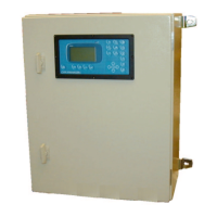
Diagram illustrating the layout of the control panel, including labels for keys, displays, and status LEDs.

Related product manuals