TECHNICAL MANUAL
CVM 2
C 5001 CV/01-99 IT
4
1 Connections
1.1 Temperature probes
The connected temperature probes are 3, or 4 in the case of water-water heat pumps with reversing cycle on the water side.
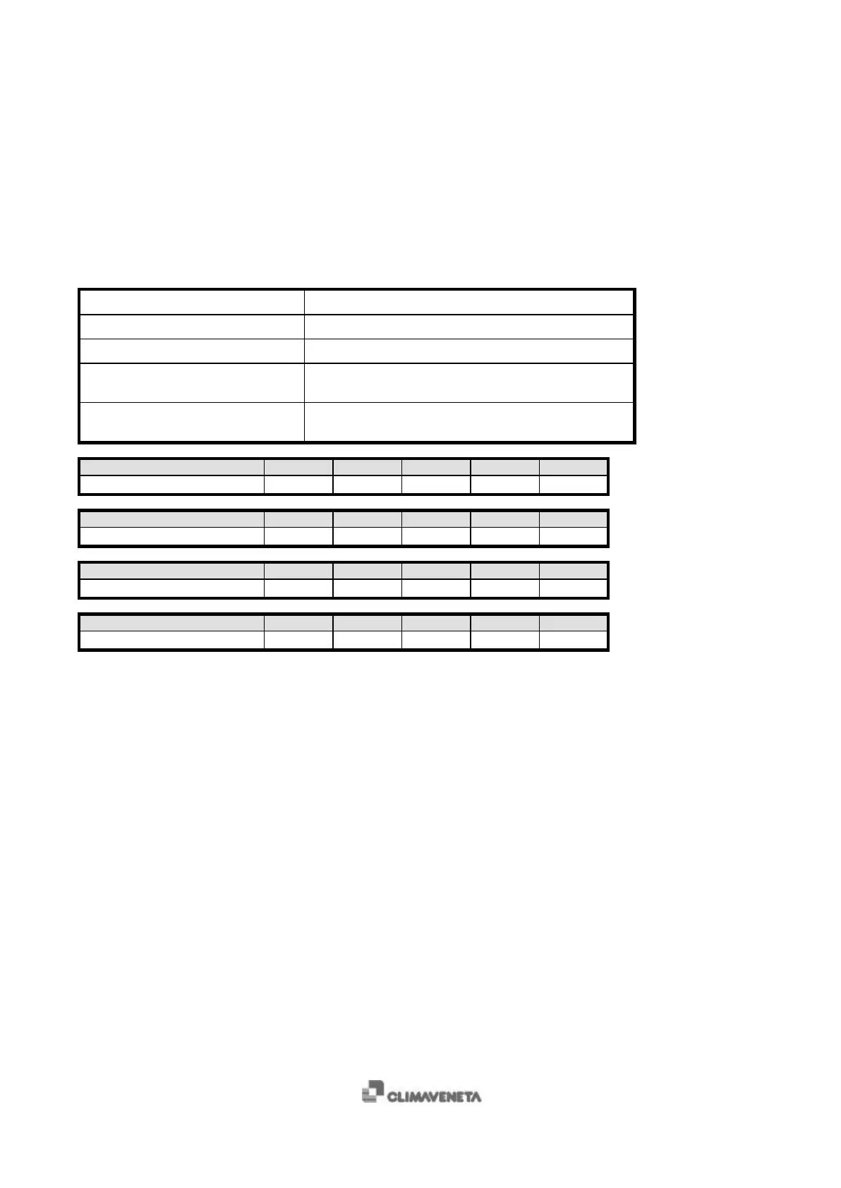
TERMINALS MEANING
1, 2 Inlet water temperature
3, 4 1
st
evaporator outlet water temperature
5, 6 2
nd
evaporator outlet water temperature (only with plate
heat exchangers)
7, 8 (only for water-water heat pumps
with reversing cycle on the water side)
Condenser inlet water temperature
Temperature [°C] -55 -50 -40 -30 -20
Resistance [Ω]
485 510 562 617 677
Temperature [°C] -10 0 10 20 25
Resistance [Ω]
740 807 877 951 990
Temperature [°C] 30 40 50 60 70
Resistance [Ω]
1029 1111 1196 1286 1378
Temperature [°C] 80 90 100 110 120
Resistance [Ω]
1475 1575 1679 1796 1896
Temperature probes verification procedure:
• disconnect the power supply to the unit;
• disconnect the probe from microprocessor’s terminals;
• use a digital Ohmmeter to measure the resistance value of the probe;
• measure the temperature near the probe cap;
• compare the resistance value measured with the one shown in the table: the corresponding temperature must be
approximately the same as the measured one.
 Loading...