TECHNICAL MANUAL
CVM 2
C 5001 CV/04-99 GB
5
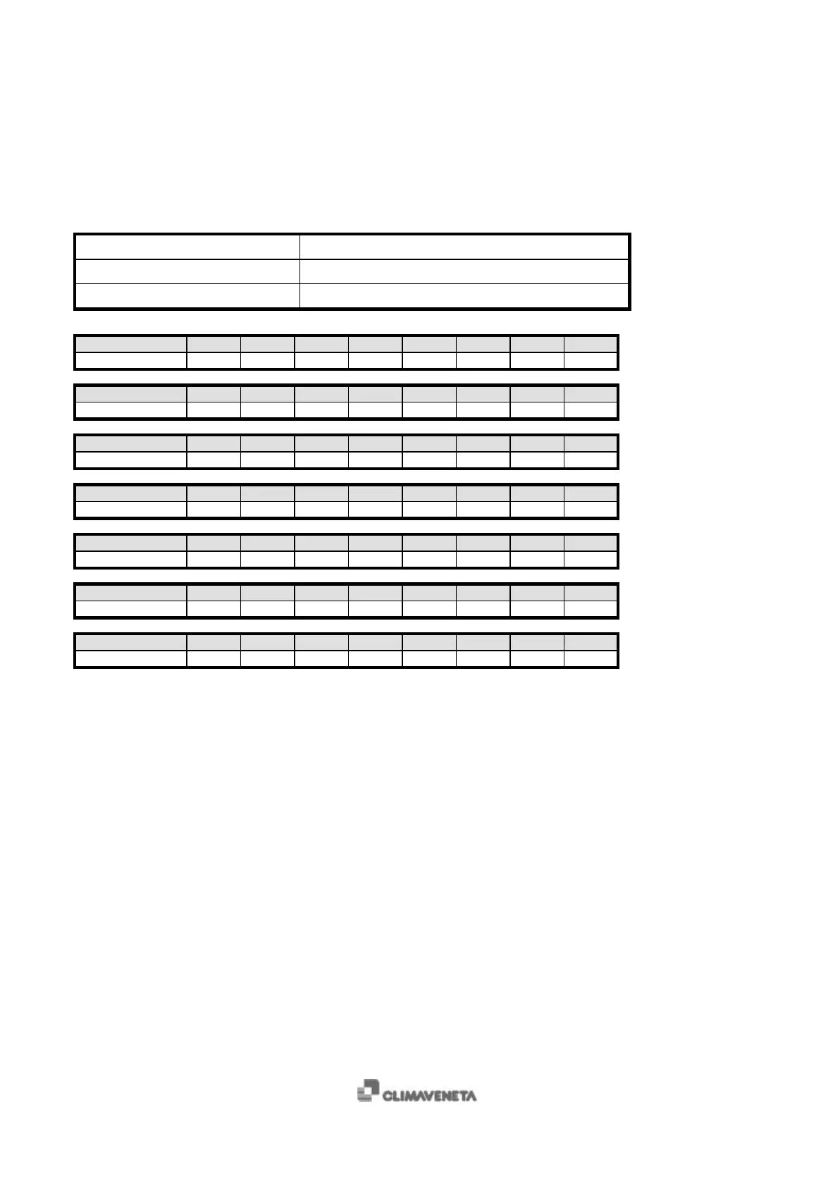
1.2 Pressure probes
There are two 4-20mA , 0-30 bar pressure probes for all the units, except for the water-water heat pumps with reversing cycle
on the water side.
TERMINALS MEANING
7, 8 1
st
circuit condensing pressure
9, 10 2
nd
circuit condensing pressure
Pressure [Bar] 0.0 0.5 1.0 1.5 2.0 2.5 3.0 3.5
Current [mA] 4.00 4.27 4.54 4.80 5.07 5.34 5.61 5.87
Pressure [Bar] 4.0 4.5 5.0 5.5 6.0 6.5 7.0 7.5
Current [mA] 6.14 6.41 6.68 6.94 7.21 7.48 7.75 8.01
Pressure [Bar] 8.0 8.5 9.0 9.5 10.0 10.5 11.0 11.5
Current [mA] 8.28 8.55 8.82 9.08 9.35 9.62 9.89 10.15
Pressure [Bar] 12.0 12.5 13.0 13.5 14.0 14.5 15.0 15.5
Current [mA] 11.43 10.69 10.96 11.23 11.49 11.76 12.03 12.30
Pressure [Bar] 16.0 16.5 17.0 17.5 18.0 18.5 19.0 19.5
Current [mA] 12.56 12.83 13.10 13.37 13.63 13.90 14.17 14.44
Pressure [Bar] 20.0 20.5 21.0 21.5 22.0 22.5 23.0 23.5
Current [mA] 14.70 14.97 15.24 15.51 15.77 16.04 16.31 16.58
Pressure [Bar] 24.0 24.5 25.0 25.5 26.0 26.5 27.0 27.5
Current [mA] 16.84 17.11 17.38 17.65 17.92 18.18 18.45 18.72
Pressure transducer verification procedure:
• switch off the compressors and leave the unit with only the “ON/OFF switch” button ON;
• disconnect the cable from terminal 7 or 9 of microprocessor, depending on the probe;
• place digital milliammeter between the disconnected terminal and the cable and read the current value;
• read the pressure value using a gauge placed near the transducer;
• compare the readings with the values shown in the table.
 Loading...