Page 4 - FL-20A Instruction Manual
Model FL-20A Cable Fault Locator
Installation
Unpacking
The following items are included in the shipment:
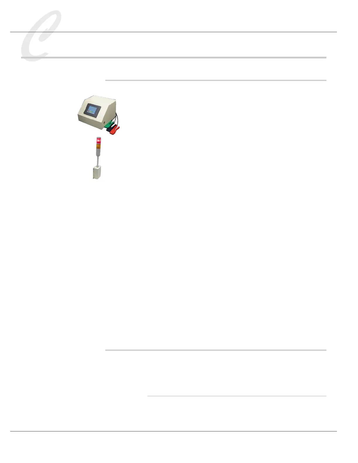
• FL-20A Cable Fault Locator, with a set of 3 test probes (red, blue and
green) connected to the back of the unit
• A green 2-position connector, to be used as a safety interlock if prod-
ucts will be tested in a cage. This will also be used during calibra-
tion.
• X3F Light Tower
• A 4-conductor cable with a 4-pin connector on one end, and a 10-pin
connector on the other, to connect the FL-20A to the X3F
• 4 bolts to mount the X3F to the FL-20A
• A Y- power cord
• 91785 FL Test Box
• (3) 92100 Probe Clip Assemblies (other sizes available)
• An instruction manual
If a printer was ordered, the following items are included:
• Printer
• Printer cable
• Power adapter
• Roll of paper, part no. 91901
Remove the FL-20A and accessories from the carton. Retain the packing
material in the event that the unit is returned for calibration or service at
some future time.
Site Preparation
Caution: The installation procedures listed below are to be performed
by qualied service personnel only. Failure to follow these procedures
may result in danger to personnel and damage to equipment.
Caged Operation
Cables under high voltage test can build up a deadly charge. It is common
practice to enclose cables under test in a caged area to protect workers,
with the FL-20A located outside the cage. When the FL-20A Caged