FL-20A Instruction Manual - Page 9
Model FL-20A Cable Fault Locator
FL-20A Controls
ON/OFF power switch
This switch is located on the rear panel of the unit.
Ground connection
A 10-32 grounding stud located on the rear panel of the FL-20A chassis.
Wire to earth ground as directed in the Installation section.
External safety interlock (for Caged Operation)
If cables are to be tested in a caged area with the FL-20A located out-
side, the FL-20A external safety interlock must be wired to the cage door
so that cables may be tested only when the cage door is closed. When
the external interlock is engaged and the Caged Operation setting, found
in the Settings menu, is ON, the operator will be required to momentarily
press the FL-20A safety buttons during a test, rather than press them for
the full test. Refer to the section of Caged Operation for wiring details.
The safety interlock is also required for calibration. A two-position con-
nector is supplied for this purpose. Refer to the Calibration section for
instructions.
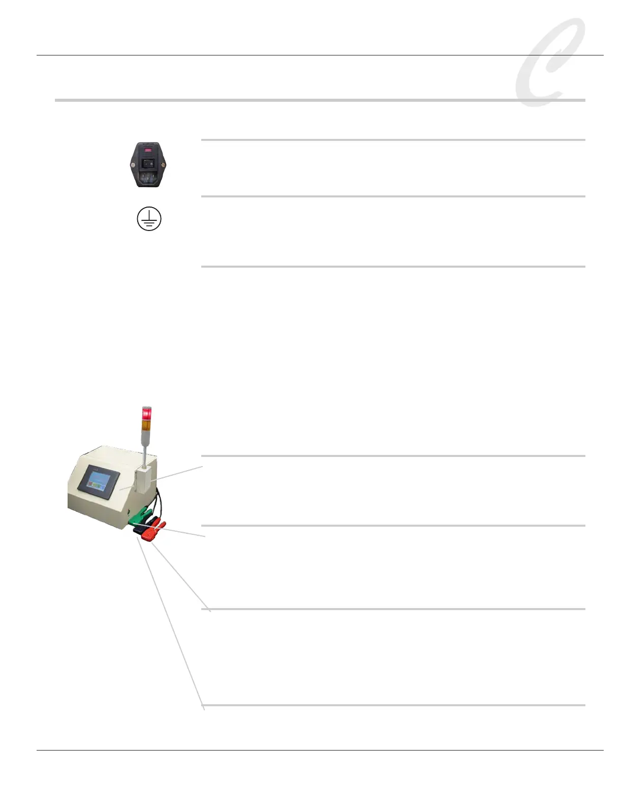
Front panel touch screen
The touch screen is used to set test parameters, run tests, and view test
results. Never press the touch screen with a tool or sharp object.
Safety buttons
Located on each side of the FL-20A, the safety buttons must be held in
during a shorts or hi-pot test. This is a safety feature that prevents the
operator from touching the charged test cable during a test.
Red and blue test probes
The red probe will connect to one end of a test conductor, and the blue
probe to the opposite end. Review the instructions in the Installation
section on how to properly strip back the conductors and insert them
into the probes. This is an important safety procedure.
Green ground probe
The green ground probe is used to make connections to the reference