FL-20A Instruction Manual - Page 19
Model FL-20A Cable Fault Locator
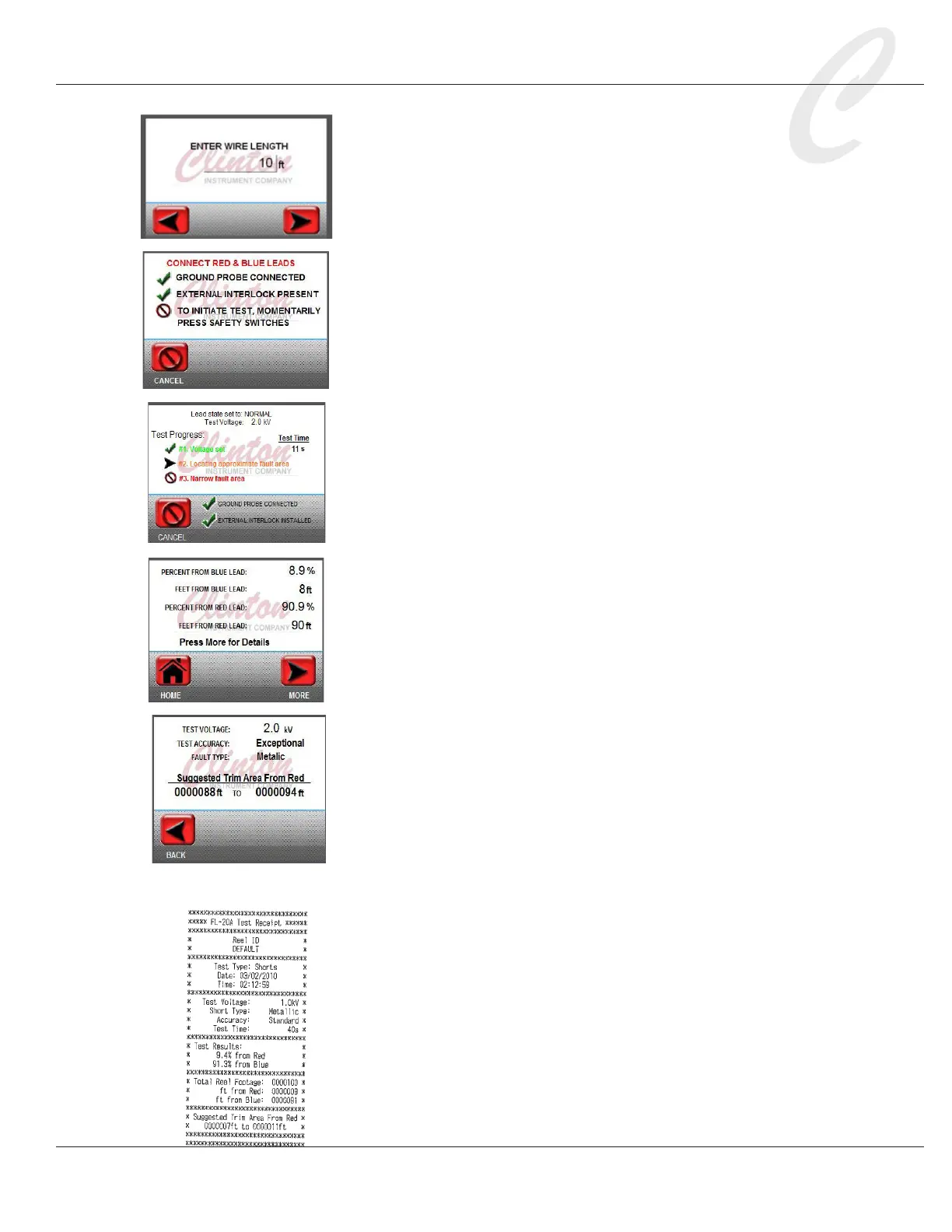
7. Enter the cable length. Press the displayed number
to access a key pad and enter the test cable length.
Press OK. The unit of measure entered previously in
the Length UOM setting will appear. Press NEXT.
The X3F yellow light will begin to ash, indicating that a test
is in progress. If the green ground probe is connected as
described in step 4, the the touch screen will display, “Ground
Probe Connected.”
8. If the Caged Operation setting is ON and the safety interlock
is open, the touch screen will note that the External Interlock is
not installed.
9. When the external interlock is closed, the test can proceed.
For Caged Operation, the touch screen will display: “To initiate
test, momentarily press safety switches.” If the Caged Operation
setting is OFF, the screen will display, “Hold Safety Switches.”
10. Press the safety switches as directed.
11. The FL-20A touch screen will indicate test progress as it tries
to locate the fault. The X3F yellow light will ash to alert that
a test is in progress, and the red High Voltage light will go on,
indicating that there is high voltage on the test cable.
12. If the Full Test setting is OFF, the rst test result screen, indi-
cating the fault distance from the red probe, will appear. Press
NEXT to continue the test, or press HOME to exit the test.
If the Full Test setting is ON, the unit will proceed through
both halves of the test, and a complete test summary report will
appear. The fault distance from the blue probe plus the fault
distance from the red probe should total the approximate length
of the test cable.
13. If the test accuracy is Standard or better, a “More” button will
display. Press More to view the test accuracy and suggested trim
area.
WARNING: Do not touch the red and blue probes or the test
cable until the red light on the X3F goes OFF. The red light indi-
cates that there is still a charge present on the test cable and the
probes. Before handling the reel under test, wait at least 10 sec-
onds, then discharge all conductors to ground. A stored charge in
the cable can be lethal.
14. A printed report showing details of the test is available if a ther-
mal printer was attached to the FL-20A and the Printer Installed
setting is ON. If the Automatic Printing setting is OFF, press
the printer icon to print the report. If the Automatic Printing
setting is ON, the report will print automatically.