FL-20A Instruction Manual - Page 21
Model FL-20A Cable Fault Locator
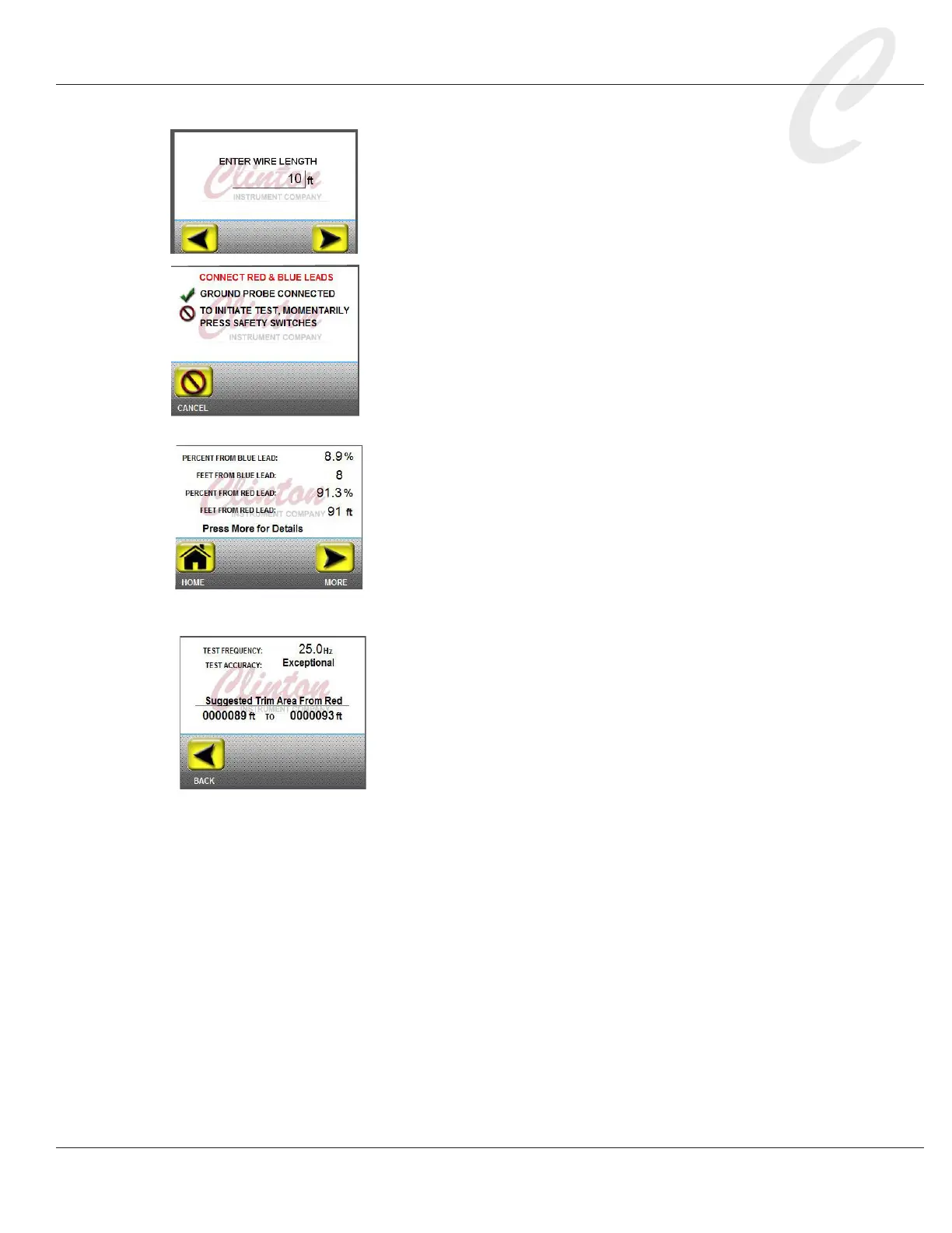
7. Enter the cable length. Press the displayed number to access a key
pad and enter the test cable length. Press OK. The unit of mea-
sure entered previously in the Length UOM setting will appear.
Press NEXT. Momentarily press the safety switches on
the sides of the unit. The X3F yellow light will begin to
ash, indicating that a test is in progress. If the green
ground probe has been connected as described in step 4,
the touch screen will display, “Ground Probe Connected.”
The X3F yellow light will ash to alert that a test is in progress,
and the FL-20A touch screen will indicate that the test has begun.
8. If the Full Test setting is OFF, the rst test result screen,
indicating the fault distance from the blue probe, will
appear. Press NEXT to automatically reverse the leads
and continue the test, or press HOME to exit the test.
9. If the Full Test setting is ON, the unit will proceed through
both halves of the test, and a complete test summary report will
appear. The fault distance from the blue probe plus the fault
distance from the red probe should total the length of the test
cable.
10. If the test accuracy is Standard or better, a “More”
button will display. Press More for Details to view the
test accuracy and suggested trim area from the red probe.