EasyManua.ls Logo

CLIVET CSRN-XHE2 User Manual

CLIVET CSRN-XHE2
58 pages
To Next Page IconTo Next Page
Page #1 background imageLoading...
Page #1 background image
M07Z40M15-02 20-09-16
CSRN-XHE2 FFA 12.2-24.4
Installation and
operating manual
High eciency “Roof top all fresh air cooled heat pump

Table of Contents

Question and Answer IconNeed help?

Do you have a question about the CLIVET CSRN-XHE2 and is the answer not in the manual?

CLIVET CSRN-XHE2 Specifications

General IconGeneral
BrandCLIVET
ModelCSRN-XHE2
CategoryAir Handlers
LanguageEnglish

Summary

General Description

Manual Overview and User Guidance

Explains the manual's purpose, user training, preliminaries, and intended use.

Unit Safety and Operational Procedures

Highlights risks, installation, maintenance, modification, and breakdown procedures.

User Training, Unit Identification, and Assistance

Reception and Handling

Unit Reception, Storage, and Handling

Details reception checks, storage, and safe unit handling and lifting.

Positioning Guidelines

Functional Spaces and Placement Criteria

Explains functional spaces purpose, safety valve considerations, and optimal placement.

Water Connections

Condensate Drain and Freezing Prevention

Details condensate drain requirements and measures against freezing.

Anti-Freeze Solution and Humidifier

Guides on using anti-freeze solutions and refers to humidifier accessories.

Aeraulic Connections

Treated Air Channelling and Comfort

Covers channel surfaces, thermal isolation, and diffuser placement for comfort.

Electrical Connections

Electrical Data, Connections, and Safety

Explains electrical data, connection steps, and safety precautions.

Signals, Data Lines, and Power Input

Provides guidelines for laying signal cables and managing power input.

Customer Connection Signals and SA5 Input

Wall Mounted Electronic Room Control Installation

Communication Module Options

Start-up Procedures

General Start-up and Preliminary Checks

Outlines general procedures, safety checks, and preliminary checks before start-up.

Detailed Unit Start-up Sequence

Provides a detailed sequence of operations for unit start-up.

Circuit Checks: Refrigeration, Water, Electric

Compressor Heaters and Voltage Verification

Specifies compressor heater requirements and voltage checks during operation.

Compressor, ECO Mode, and Set-Point Compensation

Fire Alarm Configuration and Low Temperature Operation

Start-up Report Data Collection

Emphasizes identifying operating conditions for long-term unit control.

Control Interface

Setpoint Adjustment and Key Functions

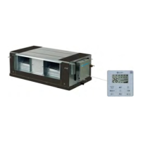
Explains setpoint adjustment, button functions, and display meanings.

Thermostat Button Lock/Unlock

Describes how to lock and unlock the thermostat buttons.

Mode Change and ON-OFF Control

Parameter Access and Day Modification

Time Band and ON/OFF Scheduling

Status Monitoring

Accessing and Navigating Status Menus

Instructions to access and navigate the main status menu.

Status Code and Description Table

Table listing status codes, their descriptions, and units.

Alarms Management

Alarm Display and Reset Procedures

Explains alarm display, cause identification, and reset steps.

Installer Access to Stored Alarms

Instructions for installers to access and view stored alarms.

Alarm Codes Reference (A001-A037)

Alarm Codes Reference (A038-A074)

Alarm Codes Reference (A075-A097)

Maintenance Schedule

General Maintenance Overview and Precautions

Explains maintenance benefits and pre-check procedures.

Inspection Frequency and Procedures

Provides a table detailing inspection frequencies for various checks.

Unit Booklet and Standby Mode Operations

Electric Fan and Outdoor Coil Maintenance

Lists checks for fans and cleaning of the outdoor air coil.

Condensation Basin, Compressor, and Heaters Maintenance

Air Filter Maintenance and Replacement

Accessory References: Filters & Humidifier

Refers to accessories for high-efficiency air filter and humidifier details.

Room Control Unit Maintenance

Describes detaching the keypad for maintenance operations.

Accessories

Accessory Configurations and Heater Humidifier

Lists configurations and covers heater humidifier startup and maintenance.

Immersed Electrode Humidifier Water Requirements

Electronic Filters

Filter Contaminants and Maintenance Materials

Lists filtered contaminants and materials needed for filter maintenance.

Ionisation Wire Maintenance Procedures

Covers cleaning and replacement of ionization wires in electrostatic cells.

F7 Highly Efficient Filter Replacement

Modulating Condensation Gas Heating Module

System Maintenance Booklet & Gas Connection

Outlines booklet requirements and gas connection standards.

Electrical Connections Diagram for Gas Module

Shows a diagram for electrical connections to the unit and gas module.

Gas Module Installation Steps

Decommissioning Procedures

Unit Disconnecting and Component Recovery

Instructs authorized personnel on unit disconnection and recovery of components.

Dismantling, Disposal, and EC RAEE Compliance

Specifies unit disposal and compliance with the EC RAEE directive.

Residual Risks Overview

General and Handling Risks

Introduces common risks, danger zones, and handling precautions.

Installation and General Safety Risks

Lists risks from incorrect installation and general anomalies.

Electric, Moving Parts, and Refrigerant Risks

Details risks associated with electrical, moving parts, and refrigerant.

Hydraulic Parts Risks

Mentions risks of leaks or water projection from hydraulic components.

Technical Data

Fresh Air Supply (CBFFA) Configuration Data

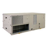
Presents technical data for fresh air supply configurations.

Cooling and Heating Operating Ranges

Sound Levels

Dimensional Drawings and Spaces

Functional Spaces Requirements

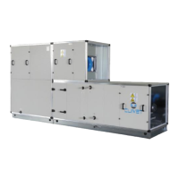
Explains the importance of functional spaces for operation and maintenance access.

Size 12.2 - 16.2 CBFFA Dimensions

Displays dimensional drawings and weight distribution for specific models.

Size 12.2 - 16.2 Combustion Module Dimensions

Size 12.2 - 16.2 CCFFA Dimensions

Size 12.2 - 16.2 Combustion Module CCFFA Dimensions

Size 20.4 - 24.4 CBFFA Dimensions

Size 20.4 - 24.4 Combustion Module CBFFA Dimensions

Size 20.4 - 24.4 CCFFA Dimensions

Size 20.4 - 24.4 Combustion Module CCFFA Dimensions

Related product manuals