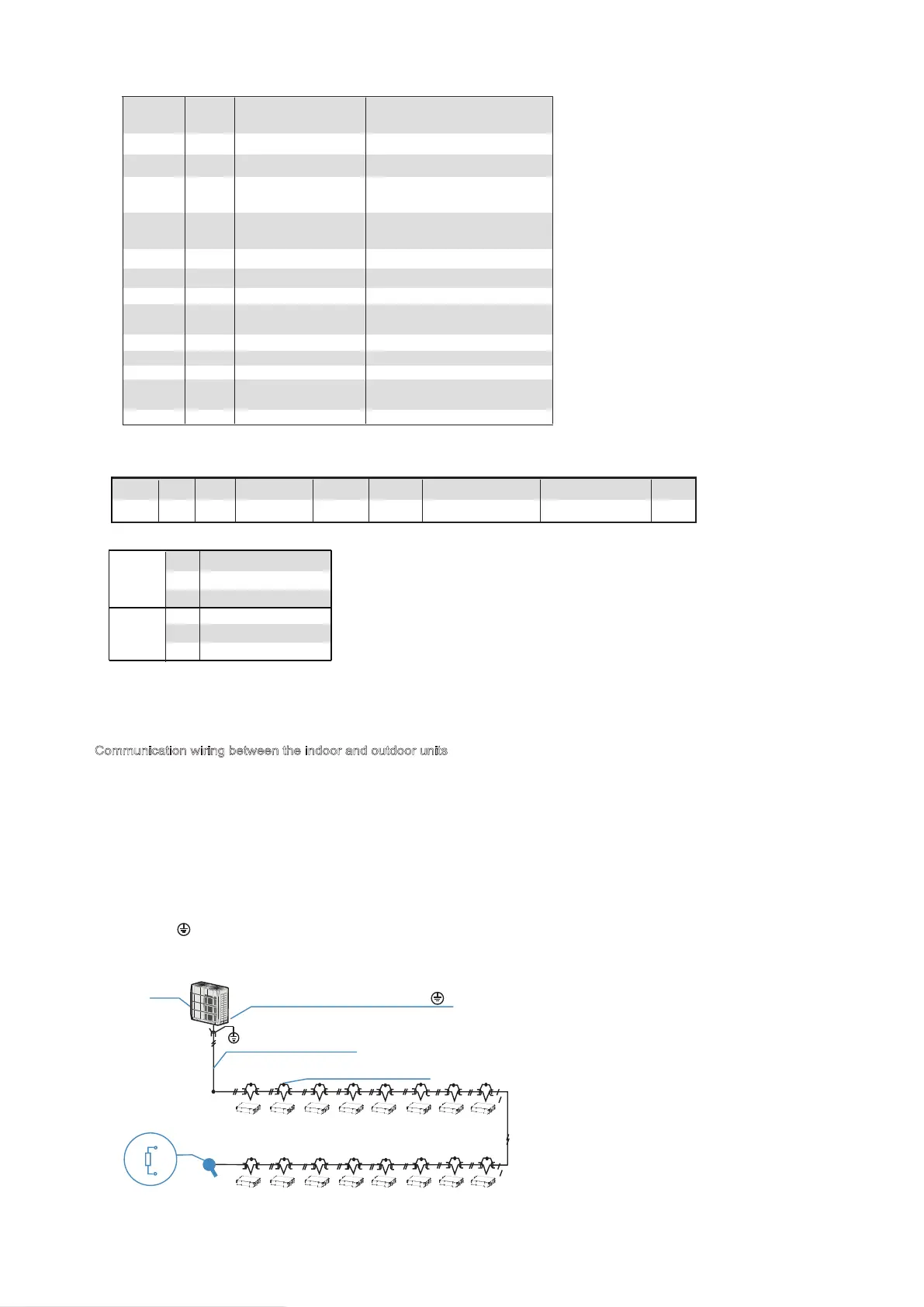
Communication wiring between the indoor and outdoor units
The HRV and outdoor units communicate via the RS485 serial port.
The communication wiring between the HRV and outdoor units should be connected one unit after
another in a daisy chain from the outdoor unit to the final HRV unit. And the shielded layer must be
properly grounded, and a build-out resistor must be added to the last HRV unit to enhance the stability
of the communication system.
Incorrect wiring such as a star connection or a closed ring will cause instability of the communication
system and system control anomalies.
Use a three core shielded wire (greater than or equal to 0.75 mm2) for the communication wiring
between the indoor and outdoor units. Make sure the wiring is connected correctly. The connecting lead
for this communication wire must come from the master outdoor unit.
All shielded wiring in the network are interconnected, and will eventually connect to earth at the same
point " ”.
Terminal Definition
Table 4-4
Code and Definitions
Table 4-3
Show on
centralized controller
Unit is ON
Unit is OFF
Operation
lamp
Indoor temperature
sensor error
Outdoor temperature
sensor error
EEPROM error
DC fan motor error
Explanation
○
●
★
★
★
★
★
★
/
/
/
/
E2
4
E5(new protocol)
EF(old protocol)
6 E7
8 E6
10 OFF LINE Without address
Communication error
with ODU
12
E1
NOTE:
●:Light ; ○:Extinguish ; ★:Quick flash
Flashing
times
★
★
★
14
16
18
E9
EU
FC
error with sensor board
error with CO2 sensor
wire controller
communication failure
Ip address Conflict
Ed Outdoor unit failure
reserved
Dry contact
(Out put)
Dry contact
(In put)
CN31
CN16
CN26
CN14
CN15
CN20
Remote ON/OFF
Force to exhaust air mode
Signal for inlet air Pre-heat
Alarm
Reserved
COD
E
NAME
Outdoor temp. SensorP Q E X Y E X1X2
CN8 CN9 CN32 CN33
- D1D2E
CN7 CN3 CN4
Indoor temp. Sensor
CN21
-
(P Q E)
(P Q E)
Only the last indoor unit requires adding
the build-out resistor at P and Q.
(open)
Indoor and
outdoor units
Communication wire
Connecting the shielded
layer of the shielded wire
(Connect the shielded end of the shielded wire to the
electronic controller box sheet metal " " here)
Signalling line
between outdoor units
Outdoor
unit
P
Q
Build-out
resistor
Communication wiring between the indoor unit and wired controller
The wired controller and the indoor unit can be connected in different manners, depending on the forms of
communication.
1. For a bidirectional communication mode:
Use 1 wired controller to control 1 indoor unit or 2 wired controllers (one master and one slave
controller) to control 1 indoor unit.(see Fig.4-4)
Use 1 wired controller to control multiple indoor units or 2 wired controllers (one master and one slave
controller) to control multiple indoor units. The maximum number of connections is 16.(see Fig.4-5)
2. For single direction communication mode:
Use 1 wired controller to control 1 indoor unit
The X1/X2, D1/D2 ports on the sides of the main control board and single direction communication port
are for different types of wired controllers.
For the specific connection method, refer to the instructions in the corresponding wired controller
manual to carry out the wiring and connections.
Handling the Electrical Wiring Connection Points
Once the wiring and connections are done, use tie straps to secure the wiring properly so that the
connection joint cannot be pulled apart by external force. The connection wiring must be straight out so
that the cover of the electrical box is level and can be closed tightly.
Use professional insulation and sealing materials to seal and protect the perforated wires. Poor sealing
may lead to condensation, and entry of small animals and insects that may cause short circuits in parts
of the electrical system, causing the system to fail.
Max voltage: 220 VAC (consistent with power
supply) / Max current: 1A
CN16 Force expulsion air mode - closed contact: function active (this input has a
higher priority than the setting given by dip-switch SW2-2 / 3);
CN26 Remote On / Off - closed contact: unit forced off / open contact: normal
management;
CN15 Alarm - contact closed: alarm active / contact open: no alarm
CN20 Signal for inlet air preheating - contact closed: function active / contact open:
function not active
 Loading...