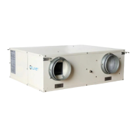
6. HRV APPLICATION
6.1 Operation principle
HRV (Heat Recovery Ventilation) employ advanced
technique and technics, the heat exchanged core forming
by special paper that be processed with chemical
treatment, which could create the optimum result in
temperature, humidity and cooling recovery.
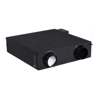
High efficiency heat exchanged core: When air flow formed
by exhaust air and outdoor air through the heat exchanged
core in cross way, because of temperature difference in
the two sides of flat partition board, the heat transmission
is occurred. In summer, outdoor air acquire cooling from air
exhaust to decrease environment temperature; In winter,
outdoor air acquire heat from air exhaust to increase
temperature, that is to say, it realizing the energy recovery
during air exhaust process to exchange the heat in heat
exchanged core to outdoor air.
6.2 Pay Attention To The Following Items Before
Operation
6.2.1. Before start-up, please clean up the duct and check
whether all air valves and devices are normal.
6.2.2. Carefully adjust the system air valves when start-up,
control the current of motor in rated range.
6.2.3. Three-phase model without by-pass function, therefore
the fan would delay 30 seconds to start up.
6.2.4. Connect the wired controller
Wired controller should be installed according to wired
controller owner’s manual, installation manual (Attached
in the package box in wire controller).
7 MAINTENANCE AND UPKEEP
7.1 During early use, one should check the fan operation
regularly.
7.2 The cleaning regulation for air filter depend on local
environment. It could be clean by vacuum dirt exhauster
or water, if heavy dust accumulates, it should use neutral
detergent to clean it, and then dry it in shady and cool
place for 20 to 30 minutes and replace it.
7.3 Clean the core at least 2 years a time by vacuum dirt
exhauster to remove dust and foreign substance in the
unit assemblies, do not touch the assemblies by
exhauster and flush by water to avoid core damage.
7.4 Check the fan every half a year to maintain the well
balance of it and check whether the axletree has loosed.
8. TRIAL RUN
8.1 Please Confirm The Following Points
Before Trial Run:
8.1.1 The unit is installed correctly completed.
8.1.2 Ducting and wiring are correctly completed.
8.1.3 The drainage is smooth.
8.1.4 The heating insulation works well.
8.1.5 The ground wiring is connected correctly.
8.1.6 The power voltage fits the rated voltage of HRV.
8.1.7There is no obstacle at the outlet and inlet of HRV.
8.2 Control The HRV By Wired controller,
Operate It According To Wired controller
Owner’s Manual.
8.2.1 Whether the switch on the remote controller works well.
8.2.2 Whether the room temperature is adjusted well.
8.2.3 Whether the indicator lights normally.
8.2.4 Whether there is vibration or abnormal noise during
operation.
Communication wiring between the indoor and outdoor units
The HRV and outdoor units communicate via the RS485 serial port.
The communication wiring between the HRV and outdoor units should be connected one unit after
another in a daisy chain from the outdoor unit to the final HRV unit. And the shielded layer must be
properly grounded, and a build-out resistor must be added to the last HRV unit to enhance the stability
of the communication system.
Incorrect wiring such as a star connection or a closed ring will cause instability of the communication
system and system control anomalies.
Use a three core shielded wire (greater than or equal to 0.75 mm2) for the communication wiring
between the indoor and outdoor units. Make sure the wiring is connected correctly. The connecting lead
for this communication wire must come from the master outdoor unit.
All shielded wiring in the network are interconnected, and will eventually connect to earth at the same
point " ”.
Communication wiring between the indoor unit and wired controller
The wired controller and the indoor unit can be connected in different manners, depending on the forms of
communication.
1. For a bidirectional communication mode:
Use 1 wired controller to control 1 indoor unit or 2 wired controllers (one master and one slave
controller) to control 1 indoor unit.(see Fig.4-4)
Use 1 wired controller to control multiple indoor units or 2 wired controllers (one master and one slave
controller) to control multiple indoor units. The maximum number of connections is 16.(see Fig.4-5)
2. For single direction communication mode:
Use 1 wired controller to control 1 indoor unit
The X1/X2, D1/D2 ports on the sides of the main control board and single direction communication port
are for different types of wired controllers.
For the specific connection method, refer to the instructions in the corresponding wired controller
manual to carry out the wiring and connections.
Handling the Electrical Wiring Connection Points
Once the wiring and connections are done, use tie straps to secure the wiring properly so that the
connection joint cannot be pulled apart by external force. The connection wiring must be straight out so
that the cover of the electrical box is level and can be closed tightly.
Use professional insulation and sealing materials to seal and protect the perforated wires. Poor sealing
may lead to condensation, and entry of small animals and insects that may cause short circuits in parts
of the electrical system, causing the system to fail.
 Loading...