4. WIRING
220-240V/50Hz
see 10. Electrical
Characteristics table
2.5
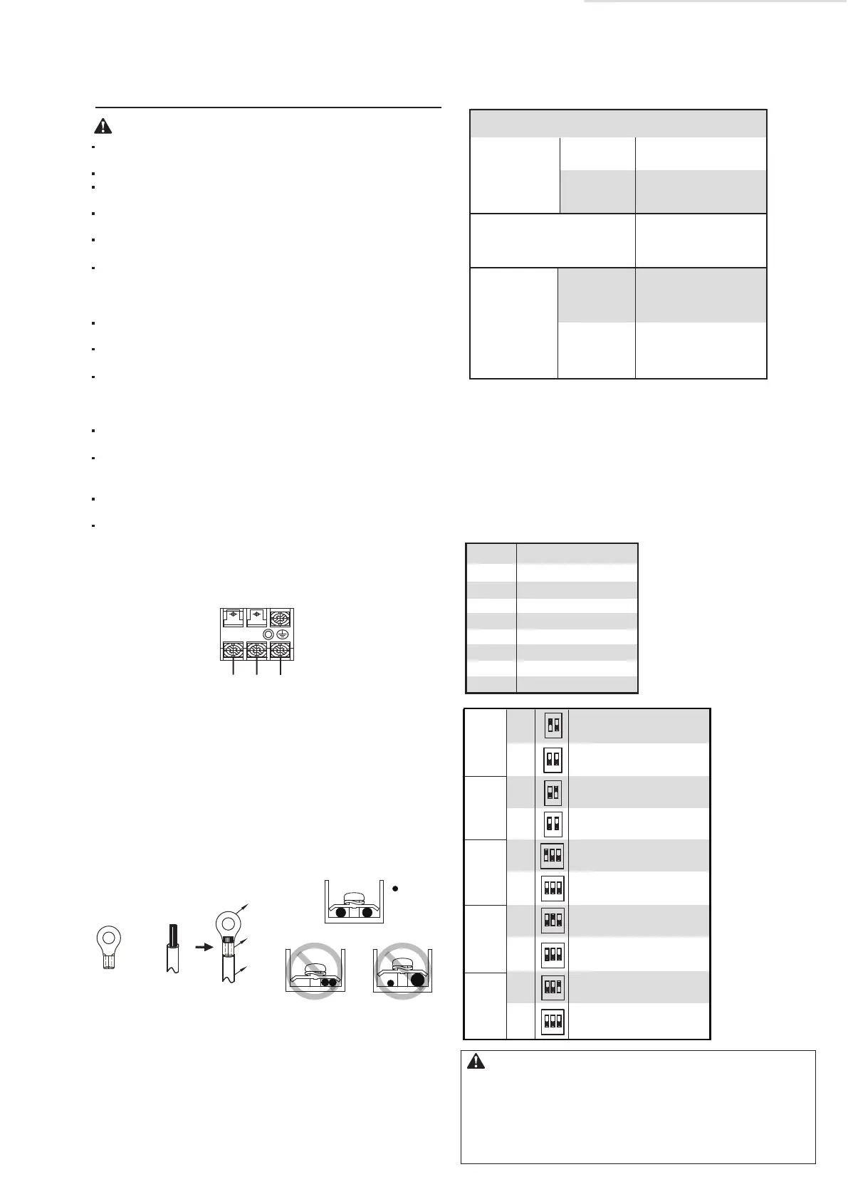
4.1 Electric data Specification
Table 4-1
Power supply
Phase
Voltage
/frequency
Input current
Main switch
/fuse(A)
Power supply
wireDimension
Wire’s qty
Wire
cross
-section
(mm
2
)
3 (Earthing line
should be used
yellow/green wire.)
Single phase
All the supplied parts, materials and electrical works must
comply with local regulations.
Only use copper wires.
Use a steady power supply for the air-conditioners. The
power voltage must be in line with the rated voltage.
The electrical wiring works must be carried out by a
professional technician, and must comply with the labels stated
in the circuit diagram.
Before the electrical connection works are carried out, turn
off the power supply to prevent injuries caused by electric
shock.
The external power supply circuit of the air conditioner must
include an earth line, and the earth line of the power cord
connecting to the indoor unit must be securely connected to
the earth line of the external power supply.
Leakage protective devices must be configured according to the
local technical standards and requirements for electrical and
electronic devices.
The fixed wiring connected must be equipped with an all-pole
disconnection device with a minimum 3 mm contact
separation.
The distance between the power cord and signal line must be
at least 300 mm to prevent the occurrences of electrical
interference, malfunction or damage to electrical
components. At the same time, these line must not be in
contact with the piping and valves.
Choose electrical wiring that conforms to the corresponding
electrical requirements.
Connect to the power supply only after all the wiring and
connections have been completed, and check carefully if the
connection is correct.
Warning
Communication wiring between the indoor and outdoor units
The HRV and outdoor units communicate via the RS485 serial port.
The communication wiring between the HRV and outdoor units should be connected one unit after
another in a daisy chain from the outdoor unit to the final HRV unit. And the shielded layer must be
properly grounded, and a build-out resistor must be added to the last HRV unit to enhance the stability
of the communication system.
Incorrect wiring such as a star connection or a closed ring will cause instability of the communication
system and system control anomalies.
Use a three core shielded wire (greater than or equal to 0.75 mm2) for the communication wiring
between the indoor and outdoor units. Make sure the wiring is connected correctly. The connecting lead
for this communication wire must come from the master outdoor unit.
All shielded wiring in the network are interconnected, and will eventually connect to earth at the same
point " ”.
POWER INPUT
L
N
figure of the power supply terminal
+
Power
cord
Insulation tube
Circular wiring
terminal
: Copper wire
Proper power wiring connections
When connecting to the power supply terminal, use the circular wiring
terminal with insulation.
Use power cord that conforms to the specifications and connect the
power cord firmly. To prevent the cord from being pulled out by
external force, make sure it is fixed securely.
If circular wiring terminal with insulation cannot be used, please make
sure that:
• Do not connect two power cords with different diameters to the
same power supply terminal (may cause overheating).
Fig. 4-1
Fig. 4-2
Fig. 4-3
ENC1 Settings for Capacity SW1 Setting for static pressure
• Positive Pressure: In the positive pressure mode, the supply fan
operating fan speed is higher than the exhaust fan.
• Negative Pressure: In the negative pressure mode, the exhaust fan
operating fan speed is higher than the supply fan.
• Balance Pressure: In the balance pressure mode, the supply fan
operating wind gear is equal to the exhaust fan.
Caution
Table 4-2
5
3
2
1
4
ENC1
Capacity sett ing
0
6
7
200
300
400
500
800
1000
1500
2000
Communication wiring between the indoor unit and wired controller
The wired controller and the indoor unit can be connected in different manners, depending on the forms of
communication.
1. For a bidirectional communication mode:
Use 1 wired controller to control 1 indoor unit or 2 wired controllers (one master and one slave
controller) to control 1 indoor unit.(see Fig.4-4)
Use 1 wired controller to control multiple indoor units or 2 wired controllers (one master and one slave
controller) to control multiple indoor units. The maximum number of connections is 16.(see Fig.4-5)
2. For single direction communication mode:
Use 1 wired controller to control 1 indoor unit
The X1/X2, D1/D2 ports on the sides of the main control board and single direction communication port
are for different types of wired controllers.
For the specific connection method, refer to the instructions in the corresponding wired controller
manual to carry out the wiring and connections.
Handling the Electrical Wiring Connection Points
Once the wiring and connections are done, use tie straps to secure the wiring properly so that the
connection joint cannot be pulled apart by external force. The connection wiring must be straight out so
that the cover of the electrical box is level and can be closed tightly.
Use professional insulation and sealing materials to seal and protect the perforated wires. Poor sealing
may lead to condensation, and entry of small animals and insects that may cause short circuits in parts
of the electrical system, causing the system to fail.
SW1-1
SW1-2
SW2-1
SW2-2
SW2-3
ON
OFF
ON
OFF
ON
OFF
ON
ON
OFF
OFF
HRV centralized control
HRV single unit operation
With PRO (reserved)
Without PRO (reserved)
Positive Pressure
Negative Pressure
SW2-2
Balance Pressure
1 2
ON
1 2
ON
3
1 2
ON
3
1 2
ON
3
1 3
ON
2
1 2
ON
3
1 2
ON
3
1 2
ON
1 2
ON
1 2
ON
Low static pressure
High static pressure
● After wiring, please confirm all connections are correct,
and then power to the unit.
● Pay attention to the power supply wire of three-phase
model; confirm the phase sequence of which is correct.
HRV-2B-Mi -D200~ D2000
 Loading...