Communication wiring between the indoor and outdoor units
The HRV and outdoor units communicate via the RS485 serial port.
The communication wiring between the HRV and outdoor units should be connected one unit after
another in a daisy chain from the outdoor unit to the final HRV unit. And the shielded layer must be
properly grounded, and a build-out resistor must be added to the last HRV unit to enhance the stability
of the communication system.
Incorrect wiring such as a star connection or a closed ring will cause instability of the communication
system and system control anomalies.
Use a three core shielded wire (greater than or equal to 0.75 mm2) for the communication wiring
between the indoor and outdoor units. Make sure the wiring is connected correctly. The connecting lead
for this communication wire must come from the master outdoor unit.
All shielded wiring in the network are interconnected, and will eventually connect to earth at the same
point " ”.
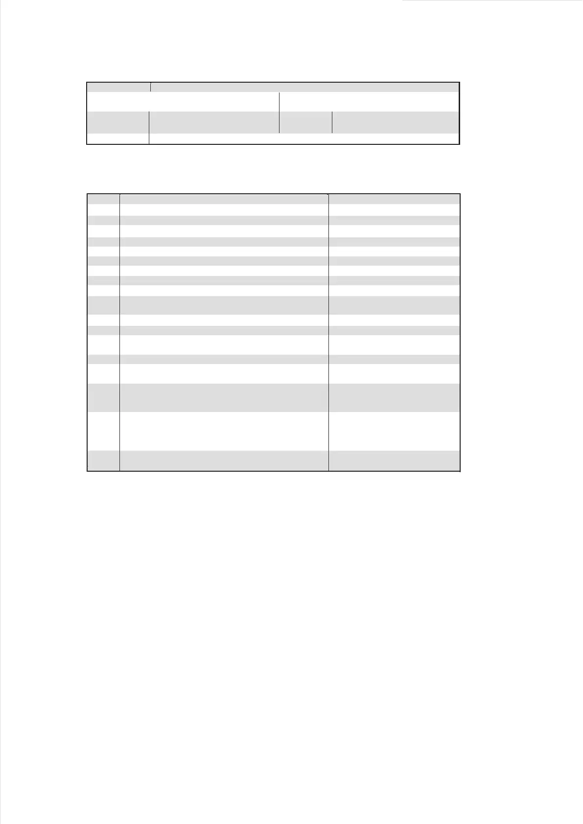
12. ERP INFORMATION
Directive (or Standard) for Regulation
ErP Directive 2009/125/EC
COMMISSION REGULATION (EU) No 327/2011
Specified Information of Fan:
category (A -D)
Efficiency category (static or total)
Efficiency grade at optimum energy efficiency point
VSD is integrated within the fan
Ref. to the Unit Nameplate
Ref. to the Unit Nameplate
Rated motor power input(s) (kW), at optimum energy
efficiency
0.1517
kw
Rated motor flow rate(s) at optimum energy efficiency
Rated motor pressure(s) at optimum energy efficiency
Rotations per minute (R.P.M)at the optimum energy
efficiency point
1320 r/min
Information relevant for facilitating disassembly,
recycling or disposal at end-of-life
all materials can be recycled
Information relevant to minimize impact on the
environment and ensure optimal life expectancy as
regards installation, use and maintenance of the fan
For installation, the clearance of
500
mm shall be kept from inlet
Measurement category A, fan is free
inlet and outlet conditions
16
Motor manufacturer
NIDEC
SHIBAURA(ZHEJIANG)CORP.
Centrifugal forward curved fan
Manufacturer’s name and place of manufacture
8
9
Table 12-1
WZDK170-38G-2 +LX-245*203*12-
48J 1320
Efficiency category (static or total)
Efficiency grade at optimum energy efficiency point
η
target=
Overall efficiencye(η
e )=
Pass or not (Criteria:η
e≧ηtarget)
Communication wiring between the indoor unit and wired controller
The wired controller and the indoor unit can be connected in different manners, depending on the forms of
communication.
1. For a bidirectional communication mode:
Use 1 wired controller to control 1 indoor unit or 2 wired controllers (one master and one slave
controller) to control 1 indoor unit.(see Fig.4-4)
Use 1 wired controller to control multiple indoor units or 2 wired controllers (one master and one slave
controller) to control multiple indoor units. The maximum number of connections is 16.(see Fig.4-5)
2. For single direction communication mode:
Use 1 wired controller to control 1 indoor unit
The X1/X2, D1/D2 ports on the sides of the main control board and single direction communication port
are for different types of wired controllers.
For the specific connection method, refer to the instructions in the corresponding wired controller
manual to carry out the wiring and connections.
Handling the Electrical Wiring Connection Points
Once the wiring and connections are done, use tie straps to secure the wiring properly so that the
connection joint cannot be pulled apart by external force. The connection wiring must be straight out so
that the cover of the electrical box is level and can be closed tightly.
Use professional insulation and sealing materials to seal and protect the perforated wires. Poor sealing
may lead to condensation, and entry of small animals and insects that may cause short circuits in parts
of the electrical system, causing the system to fail.
Description of additional items used when determining
the fan energy efficiency,such as ducts, that are not
described in the measurement category and supplied
with the fan.
 Loading...