18
Installation
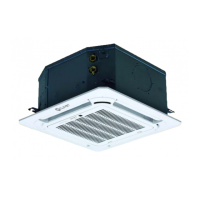
OUTDOOR AIR FAN
For the input of terminal CN8 of the new outdoor air motor
NEW FAN
CN8
M
CN23
JR6
JR6
ON - OFF
Remote
Control
CN33
ALARM
Alarm
Output
Fig. 20
– Connect the fan motor to the input, regardless of
the motor’s L/N;
– The output voltage is the power supply;
– The outdoor air motor cannot exceed 200 W or 1A;
choose the lower value;
– The new outdoor air motor will start when the
internal fan motor is running; when this motor
stops, the outdoor air motor also stops;
– When the unit goes into forced cooling mode or
power test mode,
the outdoor air motor will not work.
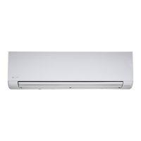
2.4.6 Assembling the panel
d
IT IS PROHIBITED TO
place the panel face down on the floor, against
a wall or on an uneven surface.
1 Remove the front grille.
– Push the two tongues towards the centre at the
same time to unlock the grille catch
2
1
Fig. 21
– Holding the grille tilted at 45°, lift it slightly and
detach it from the main body.
Fig. 22
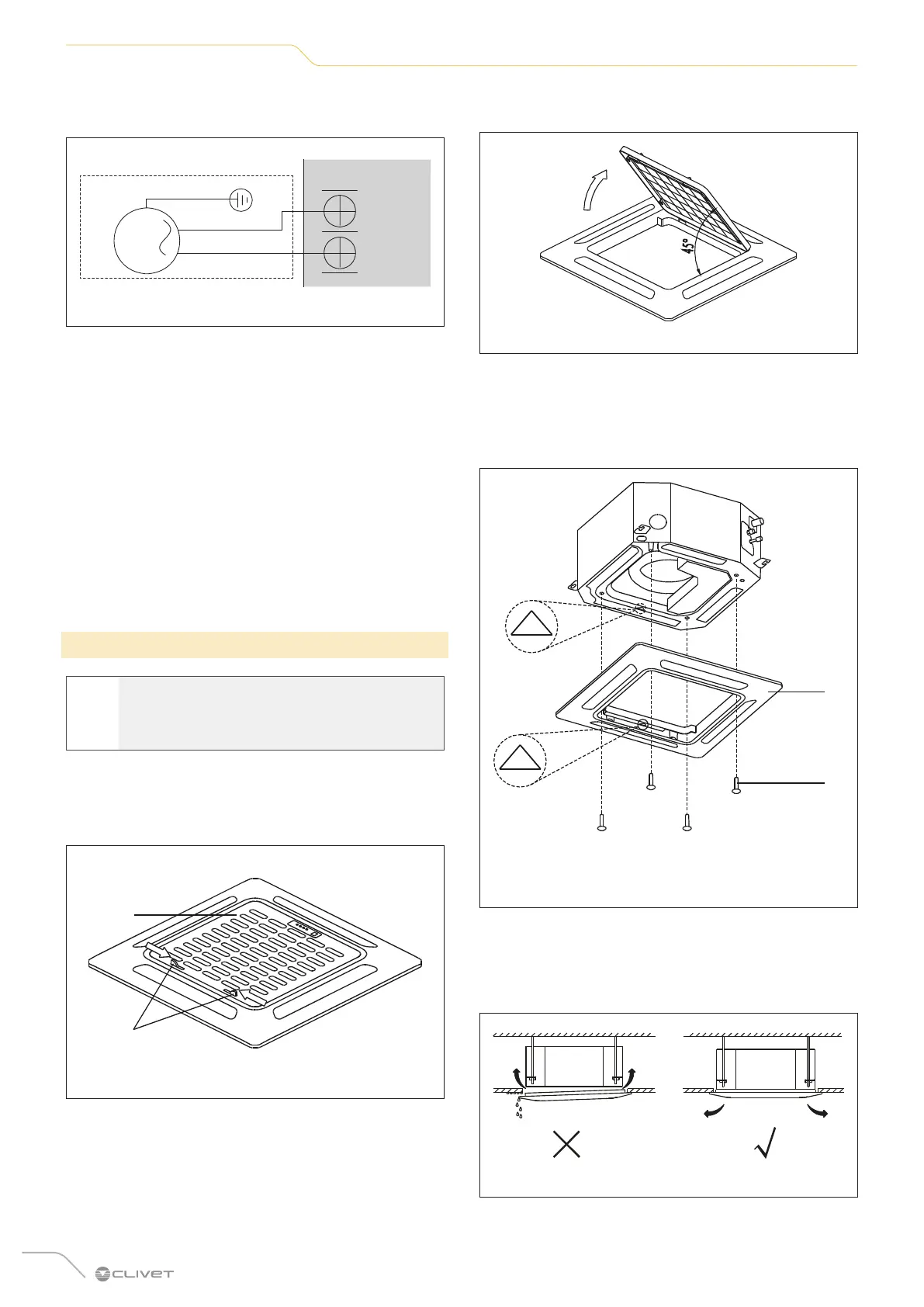
2 Install the panel
– Align “
△
” on the decorative panel with “
△
” on the
unit. Fit the decorative panel on the unit using the
screws supplied, as shown in the figure below.
2
1
1 Decorative panel
2 Screws (M5) (supplied with the panel)
Fig. 23
– After installing the decorative panel, make sure
that it is perfectly flat against the unit body. If it
is not, air could pass through the gap and cause
condensate to form.
Fig. 24
 Loading...