10 MSE-SC 65D-180F M43X41C6-03
4.6 Water lter
It must be installed immediately in the water input of the unit, in a position that is easily accessible for cleaning.
The lter never should be removed, this operation invalidates the guaranty.
4.7 Recommended connection
The installer must dene:
•
component type
•
position in system
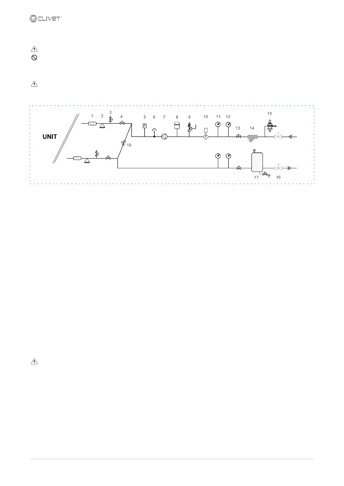
1 antivibration joints 10 Flow Switch
2 piping support 11 pressure gauge
3 exchanger chemical cleaning bypass 12 thermometer
4 shut-o valve 13 shut-o valve
5 pressure switch of the charged system 14 lter
6 vent 15 lling valve
7 Pump / circulating pump 16 shut-o valve
8 expansion vessel 17 Internal storage tank
9 safety valve 18 Cleaning system bypass
4.8 Operation sequence
Close all vent valves in the high points of the unit hydraulic circuit
Close all drain valves in the low points of the unit hydraulic circuit:
•
Heat exchangers
•
Pumps
•
collectors
•
storage tank
•
free-cooling coil
1. Carefully wash the system with clean water: ll and drain the system several times.
2. Apply additives to prevent corrosion, fouling, formation of mud and algae.
3. Fill the plant
4. Execute leakage test.
5. Isolate the pipes to avoid heat dispersions and formation of condensate.
6. Leave various point of service free (wells, vent-holes etc).
Neglecting the washing will lead to several lter cleaning interventions and at worst cases can cause damages to the exchangers and the
other parts.
 Loading...