23
Electrical connections
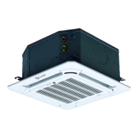
3.3.1 Communication wiring between the
indoor and outdoor units
– The indoor and outdoor units communicate via the
RS485 serial port.
– Wire the communication bus of the indoor and
outdoor units in a daisy-chain configuration from
the master outdoor unit to the last indoor unit. The
shielding must be connected properly to earth at
one point.
– To increase the stability of the communication system,
add a resistor to the last indoor unit See “Fig. 26”.
– Do not use star or closed-loop connections
because they are incorrect: they cause instability
in the communication system and faults in the
control system.
– Use a three-pole shielded cable (0.75 mm
2
or
more) for the communication wiring between the
indoor and outdoor units. Ensure that the wiring
is connected properly. The connection for this
communication cable must come from the main
outdoor unit.
– Install a 120 Ohm termination heater between
terminals P-Q of the last indoor unit.
(P Q E)
(P Q E)
P
Q
A
B
C
E
F
G
H
D
A Outdoor unit
B
All shielded cable terminals must be connected to the
metal plate of the electrical panel
C Signal cables between indoor and outdoor units
D Connect all shielding layers of shielded cables
E Communication cable for indoor and outdoor units
F Built-in heater
G Open
H The unit installed must have a suitable heater in
terminals P, Q
Fig. 26
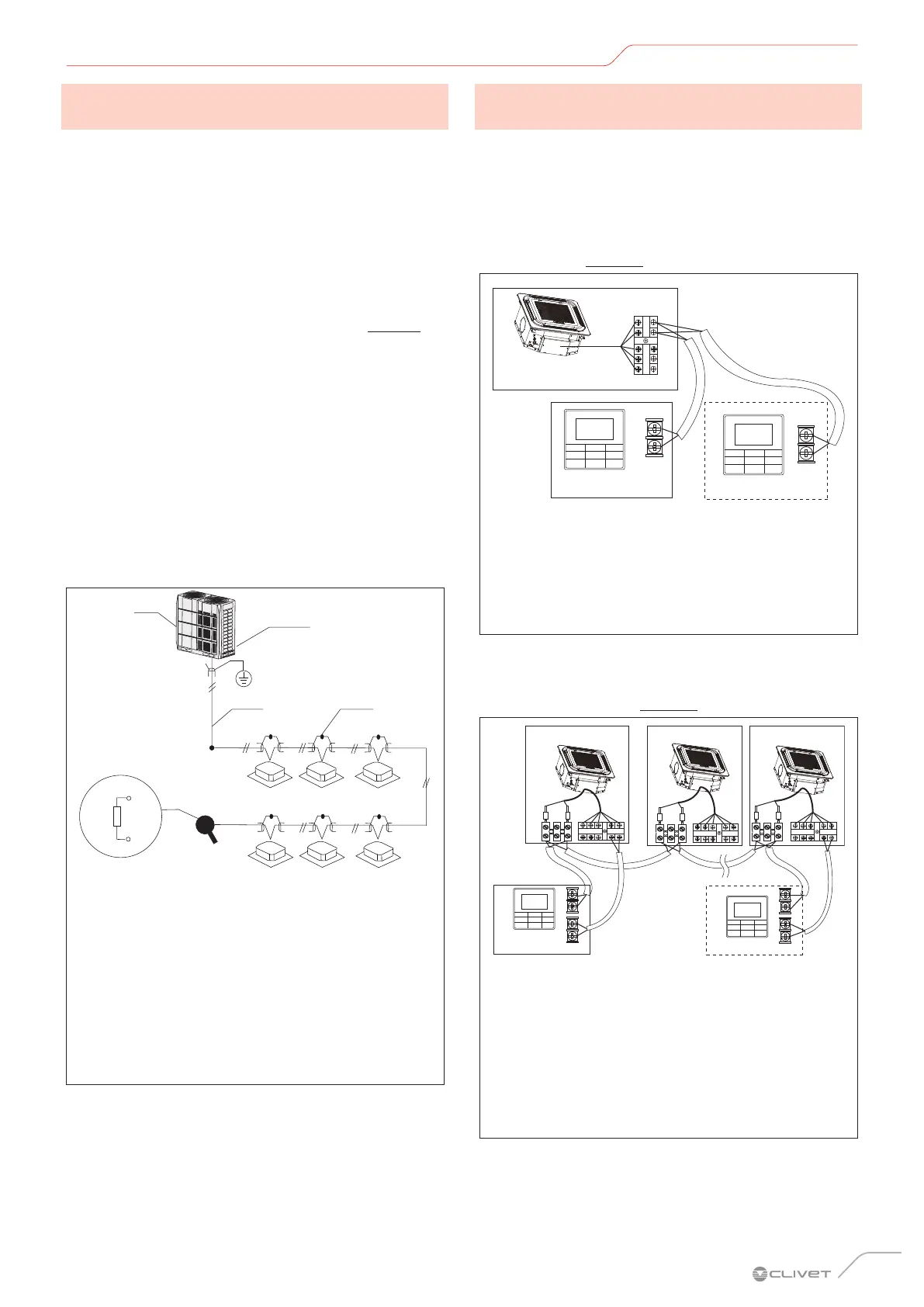
3.3.2 Communication wiring between the
indoor unit and the wired controller
The wired controller and the indoor unit can be connected in
different ways, depending on the forms of communication.
1 For a two-way communication mode:
– Use 1 wired controller or 2 wired controllers
(one main and one secondary) to control 1 indoor
unit (See “Fig. 26”);
X2
X1 X2
X1
P Q E X1 X2
A
B
C
A Indoor unit 1
B Wired controller 1
C Wired controller 2
D Master wired controller
E Slave wired controller
Fig. 27
– Use 1 wired controller or 2 wired controllers
(one main and one secondary) to control multiple
indoor units (See “Fig. 28”);
X2
X1
D2 D1
X2 X1 D2 D1
D1
D2
D1
D2
P Q E X1 X2
P Q E X1 X2
D1
D2
P Q E X1 X2
D
F
A Indoor unit 1
B Indoor unit 2
C Indoor unit n (n≤16)
D Wired controller 1
E Master wired controller
F Wired controller 2
G Slave wired controller
Fig. 28
 Loading...