22
Electrical connections
Refer to the tables below for power cable specifications.
Electrical characteristics of indoor units
Capacity
Power supply IFM
Hz Volts MCA MFA kW FLA
1.7 kW
50
50/60
220-
240
0.42 15 0.37 0.344
2.2kW 0.43 15 0.37 0.344
2.8kW 0.43 15 0.37 0.344
3.6kW 0.48 15 0.37 0.344
4.5kW 0.48 15 0.37 0.344
5.2KW 0.60 15 0.37 0.344
Abbreviations:
MCA: Minimum circuit Amps
MFA: Maximum fuse Amps
IFM: Indoor unit fan motor
kW: Motor rated power
FLA: Full load Amps
1 Select the individual cable diameters (minimum value)
for each unit based on the table below:
Rated current
of the appliance
(A)
Nominal section area (mm
2
)
Flexible cables
Fixed wiring
cable
≤ 3 0.5< ... ≥0.75 1< ... ≥2.5
3< ... ≥6 0.75< ... ≥1 1< ... ≥2.5
6< ... ≥10 1< ... ≥1.5 1< ... ≥2.5
10< ... ≥16 1.5< ... ≥2.5 1.5< ... ≥4
16< ... ≥25 2.5< ... ≥4 2.5< ... ≥6
25< ... ≥32 4< ... ≥6 4< ... ≥10
32< ... ≥50 6< ... ≥10 6< ... ≥16
50< ... ≥63 10< ... ≥16 10< ... ≥25
2 The maximum permissible variation of the voltage
range between phases is 2%.
l
WARNING
Choose the power cable and wiring with reference
to the laws and regulations in force. Assign a
professional to choose and install the wiring.
3.3 Communication wiring
– Only use shielded cables for communication wiring.
Any other type of cable can produce interference
between signals, causing the units to malfunction.
– Do not carry out electrical work such as welding
with the equipment switched on.
– All shielded wiring in the network is interconnected,
and possibly earthed at the same point.
– Do not tie refrigerant pipes, power cables and
communication cables together. If the power
cable and communication wiring are parallel, the
distance between the two lines must be 300 mm
or more to prevent signal source interference.
– The communication wiring must not form a closed
circuit.
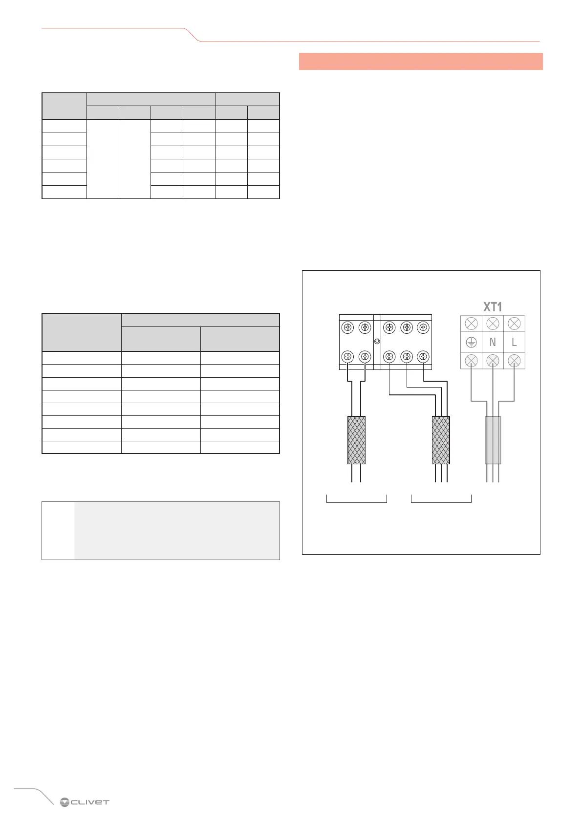
X2
X1
E
Q P
INDOOR unit terminal blocks
Signal (BUS) Signal (BUS)
to the wired
controller’s terminal
block
from the unit’s
terminal blocks
Fig. 25
 Loading...