13
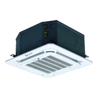
Installation
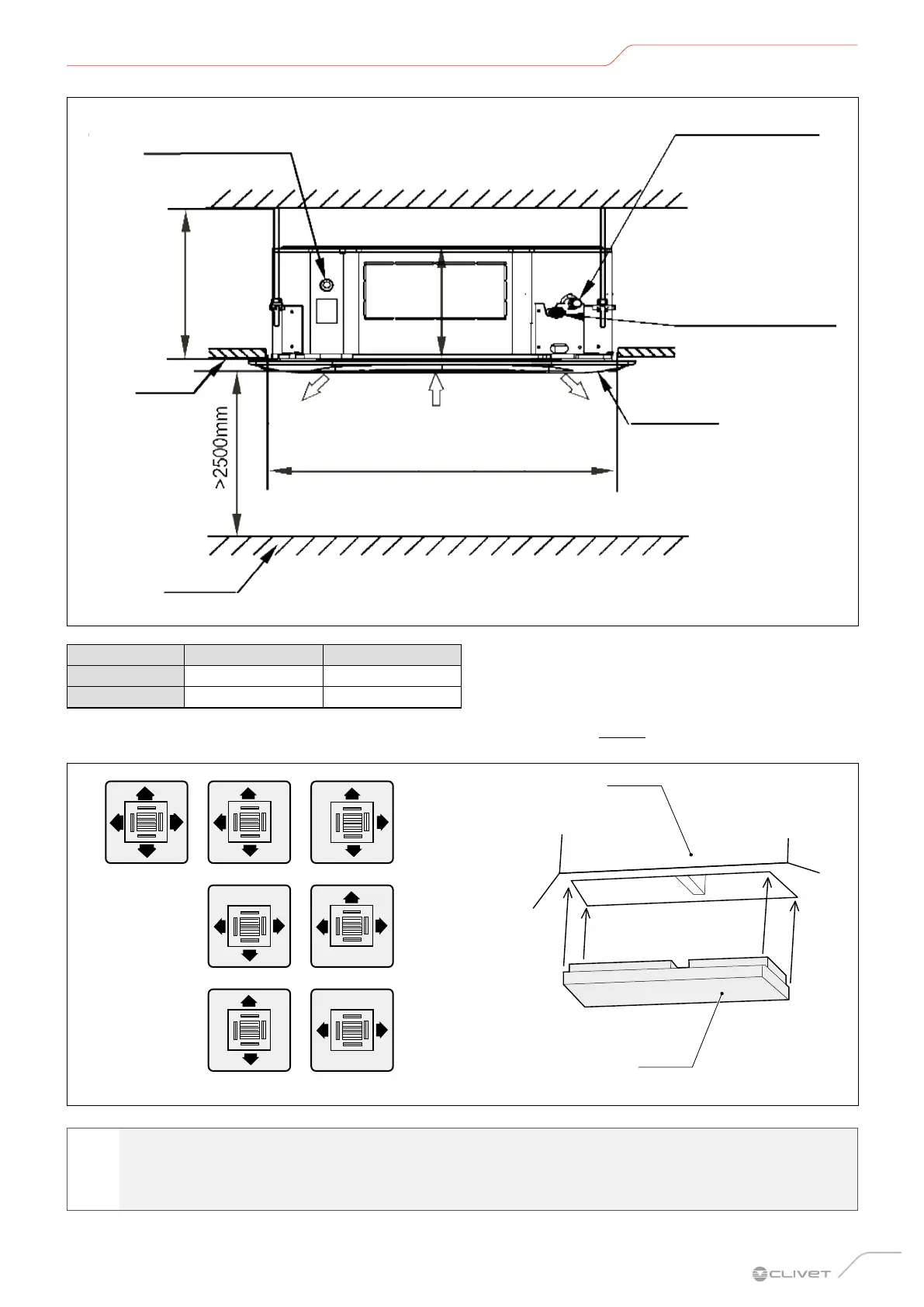
Floor
Air outlet
Ceiling
910 mm (ceiling hole)
H
A
Panel
Connect to the water
pipe outlet
Connect to the
refrigerant pipes (gas)
Connect to the
refrigerant pipes (liquid)
Air inlet
Air outlet
Fig. 4
Model A (mm) H (mm)
≤ 8.0 kW 230 ≤ 260
≤ 9.0 kW 300 ≤ 330
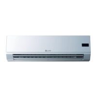
Based on the layout of the installation room, determine the direction of air flow. See “Fig. 5” for the air flow direction diagram.
To lockout the air flow, a deflector must be inserted into the unit’s casing.
Unit body
Air deflector
Fig. 5
l
WARNING
– The deflector is not included.
– Remove the panel before installing the deflector.
 Loading...