25
Electrical connections
2 For a one-way communication mode
– Use 1 wired controller to control 1 indoor unit
(See “Fig. 34”).
A
B
C
A
B
C
D
A
B
C
D
A Indoor unit 1
B Display board
C Wired controller 1
Fig. 34
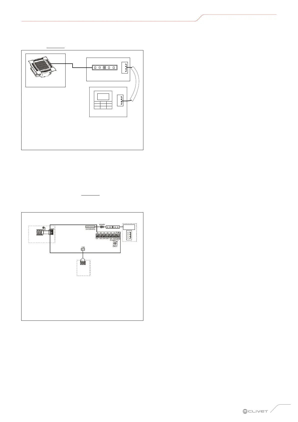
– For connection, refer to the wiring and connection
instructions in the wired controller manual.
– Ports X1/X2, D1/D2 on either side of the main
control board and the one-way communication
port (display board side) are for different types of
wired controller (See “Fig. 35”).
– Use the connection cables (accessory) to connect
ports D1/D2.
D
A
D1
D2
X2
A
B
X1
A BUS COMM. wired controller
B Wired controller
C Display board
D Main control panel
Fig. 35
– Once the wiring has been laid and the connections
have been made, fasten and secure the wiring
properly to prevent an external force from pulling
on the connection point.
– Keep the wiring straight so that there are no
differences in height that prevent the electrical
panel cover from being closed tightly.
– Use professional insulating and sealing materials
to seal and protect perforated cables. Inadequate
sealing can lead to condensation and encourage
the entry of small animals or insects which can
cause short circuits in parts of the electrical system,
thereby causing a fault.
 Loading...