Do you have a question about the CLIVET WiSAN-YME 1 S 14.1 and is the answer not in the manual?
| Cooling Capacity | 14.1 kW |
|---|---|
| COP | 4.0 |
| Refrigerant | R410A |
| Power Supply | 400V / 3Ph / 50Hz |
| Weight | 150 kg |
| Operating Temperature Range (Heating) | -10 to 24 °C |
| Heating Capacity | 16.0 kW |
General safety guidelines and required protective equipment for operations.
CAUTION for outdoor installation and requirements for site assessment.
Warns about the product containing fluorinated gases and not discharging gas.
Warns that the refrigerant is flammable and leaks can create fire risks.
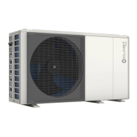
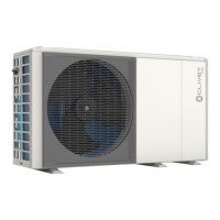
Identifies and lists the main components of the unit with corresponding numbers in diagrams.
Details the components of the hydraulic module for different unit sizes, with diagrams.
CAUTION regarding proper handling equipment, personal protective equipment, and avoiding unit damage.
Lists conditions the installation site must fulfill for proper unit operation and safety.
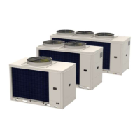
Illustrates standard installation clearances and configurations for single and multiple units.
Details the procedure for securing the unit to the base using anchor bolts and antivibration mounts.
Describes the kits available for securing the unit to a wall, including bracket and antivibration mount options.
Specifies requirements for copper piping, pressure limits, compatible components, and air vents.
Details water quality characteristics for corrosion prevention on copper and system components.
Explains the necessity of frost protection for the water circuit and potential software functions.
Details minimum water content requirements and explains expansion tank control.
Provides a step-by-step guide for filling and topping up the system with water, including pressure checks.
General warnings about fixed wiring, circuit breakers, disconnecting power, and using copper cables.
Emphasizes that electrical work must be done by a qualified electrician following diagrams and regulations.
Provides precautions like securing cables, ensuring compatibility with inverters, and using correct circuit breakers.
Advises on using ring-pressure terminals, correct cable connections, and securing wires.
Provides FLA, maximum tripping, and cable cross-section specifications for various unit sizes.
Covers water and electrical connections, configuration, and backup master unit setup for cascade systems.
Explains the smart grid and photovoltaic management functions and their operational signals.
Details the function of dip-switches on the hydraulic module control board for various settings.
Introduces the user interface (HMI) for managing unit functions, with different access levels.
Details the various icons and indicators displayed on the HMI for system status and modes.
Details functions requiring a technician's access and password for initial unit setup and adjustments.
Explains settings related to DHW mode, including enabling, disinfection, and priority.
Explains settings for enabling cooling mode, climate curve updates, and temperature limits.
Explains settings for enabling heating mode, climate curve updates, and temperature limits.
Explains how to select control based on supply water temperature or room temperature.
Details how to adjust parameters for additional heating sources like electric heaters or boilers.
Settings for configuring the unit as part of a cascade system, including start-up percentages and address adjustments.
Explains how to select and customize climate curves for automatic temperature adjustment based on outdoor conditions.
Guides on configuring network settings for unit control via the MSmartHome App and Wi-Fi module.
Describes the function of each button on the HMI keypad for navigating and controlling the unit.
Details the meaning of various icons and symbols displayed on the HMI screen.
Provides a comprehensive list of error codes, their descriptions, and corresponding Modbus codes.
Warns about the flammability of the refrigerant and potential fire risks from leaks.
Prohibits ignition sources near piping containing flammable refrigerants and stresses area inspection.
Provides a step-by-step procedure for refrigerant removal and evacuation, including purging and safety checks.
Warnings regarding electrical hazards before performing maintenance or repair work.
Lists error codes, their malfunctions/protections, and causes with corrective actions for troubleshooting.
Lists error codes, including communication errors and sensor failures.
Lists error codes related to sensors, fan errors, voltage faults, and pressure sensors.
Details error codes for low and high pressure protection, discharge temperature, and water temperature differences.
Covers error codes for module protection, fan protection, refrigerant temperature, and DC voltage.
Lists error codes related to compressor inverter faults, bus protection, and speed variations.