Do you have a question about the CLIVET WiSAN-PME 1 S and is the answer not in the manual?
Details on the manual's purpose, integral role, and recommended handling for proper installation, use, and maintenance.
Explanation of symbols used in the manual and on the unit for quick and clear information on safe operation.
Defines the intended users (User, Installer, Technical Support Service) and their responsibilities.
Describes how the manual is divided into sections, each dedicated to specific recipients.
Crucial safety warnings for operation, installation, and maintenance, emphasizing compliance with regulations.
Specific safety warnings for installation and maintenance operations involving flammable refrigerants.
Highlights the flammability of the refrigerant and associated fire risks, emphasizing leak prevention.
Procedures and checks to minimize ignition risks before and during interventions on the system.
Checks for electrical components to prevent safety risks, including capacitor discharge and exposed wires.
Guidelines for fixing sealed and intrinsically safe components to maintain safety in flammable atmospheres.
Checks for wiring to ensure it's protected against wear, corrosion, and vibration for safe operation.
Prohibits ignition sources for leak detection and specifies limitations on halogen torches.
Details on using electronic leak detectors, calibration, and suitability for flammable refrigerants.
Procedures for safely removing, evacuating, and charging refrigerant, including safety precautions.
Essential steps and considerations for safely decommissioning the unit and its components.
Requirements for labelling decommissioned units and procedures for safe refrigerant recovery.
Guidelines for safe transportation, storage, and disposal of units according to regulations.
Checks upon receipt of the unit, including refrigerant leak detection and handling instructions.
Defines the safety area around the unit, prohibiting ignition sources and specifying placement restrictions.
Specifies required clearances for installation and direction of exhaust air flow for optimal performance.
Details on the serial number label and matriculation plate for unit identification and features.
Information on the relevant regulatory framework found in the declaration of conformity.
Specifies the designed applications for the units, including outdoor installation and heating/cooling.
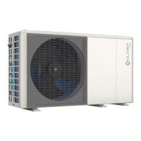
Overview of the packaged reversible air/water heat pump for heating, cooling, and DHW production.
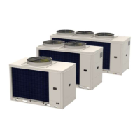
Diagrams and lists of the main components for different unit sizes (2.1-3.1 and 4.1-8.1).
Illustrations and component lists for the hydraulic module, both standard and optional configurations.
Lists the components included in the unit's package, such as manuals, probes, and fittings.
Indicates that a list of compatible accessories can be found in the technical bulletin.
Requirements for the installer, including referring to technical data and safety instructions.
Checks to perform before accepting delivery to ensure no damage and correct materials are supplied.
Recommendations for storing the unit, including temperature and humidity limits to prevent damage.
Methods for handling the unit (crane, forklift) and guidelines for safe operation and center of gravity.
Step-by-step instructions for safely removing the unit's packaging upon reaching the installation site.
Essential requirements for installers, including safety, electrical system design, and site checks.
Guidance on installing windbreaks to prevent operational problems in particularly windy locations.
Instructions to protect the outdoor air probe from direct sunlight to ensure accurate temperature readings.
Recommendations for raised bases to prevent snow accumulation obstructing air intake and exhaust.
Illustrative diagrams showing floor and suspended installation configurations for the unit.
Detailed diagrams and specifications for required clearances around the unit for various installation types.
Guidance on positioning the unit, including the use of anti-vibration mounts and fixing kits.
Instructions for managing condensate drainage, covering channelled, free drainage, and wall positioning.
Procedure for accessing internal components by removing removable access panels.
Instructions for removing the transport bracket that secures the compressor during transit.
Schematic showing the overall system layout including the unit, solar panels, DHW tank, and heating system.
Requirements for installers regarding safety instructions and hydraulic system design for water connections.
Specifies the design water flow rate must meet exchanger operating limits and be guaranteed.
Checks for compliance with minimum water content and considerations for process applications or high thermal loads.
Table detailing water quality requirements to prevent copper corrosion, including pH, hardness, and ions.
Instructions for thoroughly cleaning the system to remove residues and impurities before connecting the unit.
Guidance on insulating the hydraulic circuit to prevent condensation and heat loss during cooling and winter.
Measures to prevent freezing in the hydraulic circuit, including glycol use or heating cables.
Installation of automatic valves at lowest points to drain water and prevent freezing, with glycol considerations.
Diagrams showing the position of system supply, pressure relief valve, and system return connections.
Ensures clean piping, proper sealing, material isolation, and prevention of pipe deformation during connection.
Mandatory installation of the supplied water filter, its accessibility, and the prohibition of its removal.
Procedure for connecting the safety valve outlet to a collection system and ensuring the drain pipe is clear.
Steps for charging the system with water, including initial checks and filling until air relief valves operate.
Requirements for installers, including safety, adherence to regulations, and proper cable selection.
Details on cable inlets for high voltage and low voltage cables, and cable entry into the electrical panel.
Ensures correct connection of power supply wires, terminal block tightness, and protective devices.
Wiring diagrams for three-phase units, including standard and those with electrical resistance.
Tables for selecting correct electric cable sizes based on unit size, FLA, and resistance options.
Diagrams and terminal block references for connecting external components like boilers, pumps, and sensors.
Wiring configurations for SV1, SV2, and SV3 valves, detailing contact types and protection tripping.
Wiring diagrams for additional pumps (P_c, P_o, P_s, P_d) including contact types and cable cross-sections.
Wiring details for integrated and external electric heaters (IBH, TBH) with contact type and protection information.
Wiring for solar thermal signals, defrost/alarm states, integration heat generators, and remote ON/OFF.
Describes three methods for connecting a zone thermostat (ON/OFF, mode change) depending on the application.
Details for connecting two zone thermostats in a double zone system, managing ON/OFF and Heat-Cool functions.
Configuration and operation of the SMART GRID system for utilizing excess electricity for DHW.
Essential checks before start-up, including unit installation, power supply isolation, and tension absence.
Reference to the user interface manual for system configuration and advanced feature settings.
Procedure to access the 'For serviceman' menu for advanced settings and tests.
Instructions for verifying the proper operation of various actuators, with a list of available actuators.
Procedure to activate the vent cycle for removing air from the hydraulic circuit to prevent malfunction.
How to verify the correct operation of circulation pump, cooling, heating, and DHW modes.
Procedure to verify the minimum flow rate is guaranteed in different situations using bypass valve settings.
Requirements for technical support personnel performing maintenance, including safety and training.
A table outlining maintenance tasks and their recommended intervention frequency (1, 6, 12 months).
Recommendation to create a unit booklet for recording interventions and aiding troubleshooting.
Guidance for long periods of inactivity, including turning off power and preventing frost risk.
Procedure for safely emptying the system, requiring unit shutdown and disconnection from power.
Instructions for cleaning the unit's structure, emphasizing frequency and suitable cleaning agents.
Guidance on cleaning the air side exchanger for optimal thermal exchange, recommending regular cleaning.
Ensures water pressure is adequate and provides instructions for adding water if necessary.
Instructions for checking and cleaning the water filter, emphasizing the importance of its presence.
Checks for safety valve leakage and ensures the pressure relief pipe is correctly positioned and unobstructed.
Visual inspection of the electrical panel, checking connections tightness and cleanliness for safety.
Annual checks for glycol concentration and pH value, with actions for low pH indicating inhibitor depletion.
Procedures for safely disconnecting the unit, recovering refrigerant gas and antifreeze solutions.
Information on Waste Electrical and Electronic Equipment (WEEE) disposal according to EU directives.
Identifies common situations not controlled by the manufacturer that pose risks to people or things.
Defines the danger zone within the unit accessible only with deliberate removal of protections.
Precautions during handling operations to prevent drops or tipping, and compliance with regulations.
Potential risks from incorrect installation, including leaks, fire, and structural instability.
Warnings about contact with moving parts like fans or transmissions, requiring safety precautions.
Risks associated with refrigerant intervention, including expulsion, intoxication, and explosion hazards.
Potential risks from defects in tubing or attachments, leading to leaks or water projection.
Information on the cascade function, supporting up to 6 units (1 Master, 5 Slaves) with connection details.
Procedure to configure a backup master unit to prevent interruption and ensure system continuity.
Tables detailing heating performance metrics (capacity, power input, COP, flow rate) at various conditions.
Tables detailing cooling performance metrics (capacity, power input, EER, flow rate) at various conditions.
Energy efficiency data (SCOP, energy class, ηs) for heat pumps under average and low temperature conditions.
Specifications for compressor, oil, refrigerant, and fan performance across different unit sizes.
Data on sound power and sound pressure levels for heating and cooling modes at different operating stages.
Graphical representation of the unit's operating ranges for cooling and heating/DHW based on water and external temperatures.
Diagrams and tables showing unit dimensions, weights, and required functional spaces for installation.