34
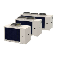
Water connections
Sizes 4.1-8.1
1
2
1 Piping
2 Water filter
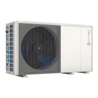
7.13 Safety valve
The outlet of the pressure relief valve must be connected to
a suitable collection system.
Discharge in pressure 3 bar,
1
2
1 Ø 16mm pressure relief valve connection
2 Drain pipe (not supplied)
7.14 Loading the plant
Once the hydraulic connections have been completed, the
system can be charged.
Before charging:
► turn the system’s main switch to “off”
► check that the system shut-off valve is closed
► open all of the system and terminal relief valves
► open the unit’s automatic air relief valve.
To fill the system:
► start filling, slowly opening the water shut-off valve
When water starts coming out of the air relief valves:
► close the valves
► continue filling up to the system pressure
► check the hydraulic tightness of the connections.
Repeat this operation after the unit has been operating
for a few hours.
Check the system pressure periodically.
The system rells when the unit is o (pump OFF).
If present, the DHW tank should only be lled when star-
ting the unit.
If the system remains charged and inoperative at outside
temperatures close to zero, freezing problems may occur.
Refer to the Hydraulic Circuit Frost Protection chapter.
 Loading...