36
Electrical connections
Remember that:
• the unit must be earthed
• all external high voltage loads, if connected to a metal
fitting or grounding port, must be earthed
• the current required for each external load must be less
than 0.2 A. If the current required for a single load is gre-
ater than 0.2 A, insert a contactor for control
• as an example, the ports on terminals “AHS1” “AHS2”, “A1”
“A2”, “R1” “R1” and “DTF1” “DTF2” only provide the switch
signal
Refer to “Connection terminal block” for the location of
the ports in the unit.
All cables are connected to high voltage lines with the
exception of the thermistor cable and user interface
cable.
8.2 Cable inlet
To access the panel, see the “Access to internal parts” section
Before removing the panel from the electrical panel,
disconnect the power supply to the unit, to the backup
heater, to the domestic hot water tank and to all the other
electrically powered components.
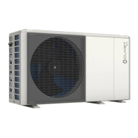
Sizes 2.1-4.1
1
2
1 Hole for high voltage cable (power supply)
2 Hole for low voltage cable (control and signal wires)
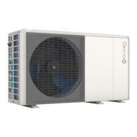
Sizes 5.1-8.1
1
2
1 Hole for high voltage cable (power supply)
2 Hole for low voltage cable (control and signal wires)
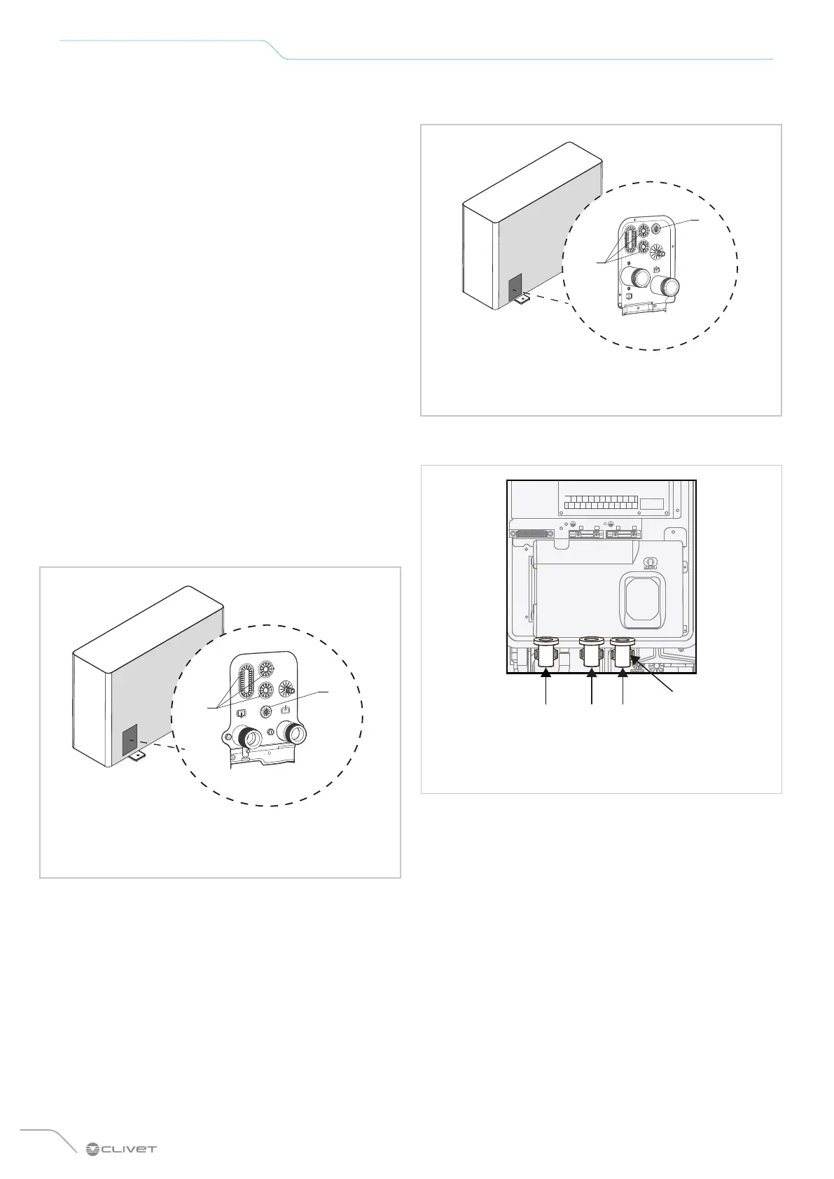
Cable entry in the electrical panel
A B
B
C
A Power supply inlet
B Signal inlet
C Cable clamps
After energising, wait 10 minutes for compressor inverter
DC bus capacitors to discharge.
The external backup heater requires a dedicated electric
circuit.
Installations with domestic hot water tank (available
as an option) and external backup heater require a de-
dicated electric circuit for the booster heater. See the
accessory sheet for the domestic hot water tank.
Connect as shown in the wiring diagrams.
 Loading...