61
Advanced applications
14. Advanced applications
14.1 Units connected in cascade
The cascade function of the system supports a maximum of
6 units, one Master and five Slaves.
14.1.1 Water connections
The hydraulic connection should preferably be an inverted
return connection for better water balance between the
different units.
It is also mandatory to install non return valves in parallel
units to stop the flow through the unit from short circuiting
when the circulator is not in operation.
14.1.2 Electrical connections
Use shielded wire in M/S cascade connections.
To ensure auto-addressing, all units must be connected to
the same power supply and evenly powered.
14.1.3 Configuration
The configuration is carried out by setting the SW9 and S3
dip-switches.
SW9: defines the Master unit.
(Only one unit needs to be configured as Master. )
S3: sets the address of the Slave units.
Each unit on the network must be assigned an address.
S3 1,2,3
1
ON
2 3 4
0/0/0 = address 0 (master units)
1/0/0 = address 1 (slave units)
0/1/0 = address 2 (slave units)
0/0/1= address 3 (slave units)
1/1/0 = address 4 (slave units)
1/0/1 = address 5 (slave units)
0/1/1 = address 6 (slave units)
1/1/1 = address 7 (slave units)
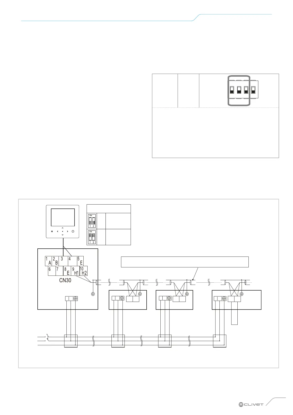
Connection diagram of the electrical control system for the cascade system (single-phase)
X/HA Y/HB
L N
L N L N
L N
Master unit
Slave unit 1
H1 H2
Slave unit 2
H1 H2
Slave unit x
H1 H2
......
ON
OFF
SW9
Slave unit
Master unit
T1 T2
Use shielded wire, the shielding layer must be earthed
Distribution
panel
Distribution
panel
Distribution
panel
External electric heater
Distribution
panel
On/Off
switch
Power supply
Only the last IDU requi-
res the addition of the
heater
H1-H2

 Loading...