33
Water connections
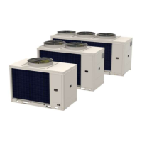
7.10 Position of connections
Sizes 2.1-3.1
3
1
2
1 1” system supply
2 Ø 16mm pressure relief valve
3 1” system return
Sizes 4.1-8.1
3
1
2
1 1 1/4” system supply
2 Ø 16mm pressure relief valve
3 1 1/4” system return
7.11 Hydraulic connection
Ensure that:
• clean piping with no moisture, air, dirt or dust is used
• the end of the pipe is kept downwards when removing
burrs
• the end of the pipe is covered when passing it through a
wall to prevent dust and dirt from entering
• thread sealant is used to seal the connections that must
withstand the pressures and temperatures of the circuit
• the two types of materials are isolated from each other to
prevent galvanic corrosion when using non-copper metal
piping
• the piping is not deformed by using excessive force or
unsuitable tools during connection: this could cause the
unit to malfunction.
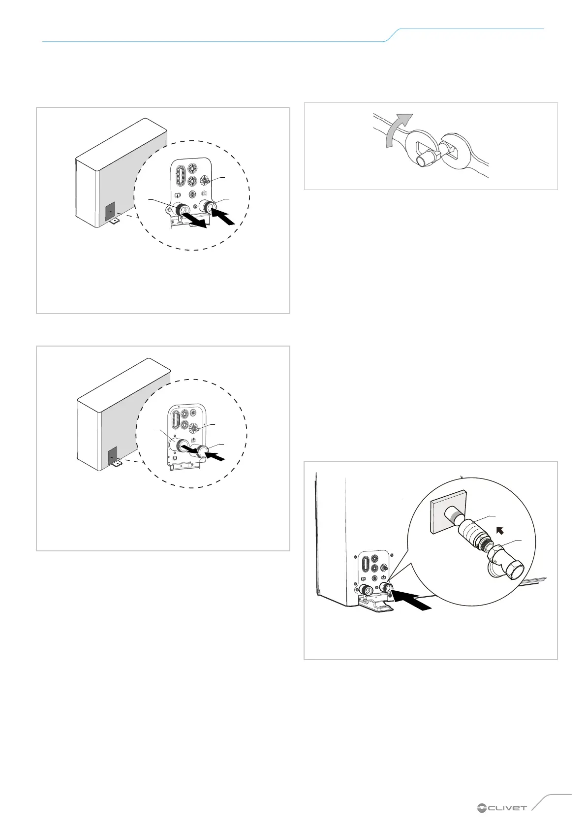
Always use the wrench and counter wrench method in
tightening operations.
7.12 Water filter
A water filter is supplied with the unit.
As an option, a sludge remover lter is available as an acces-
sory.
Installation of the lter is mandatory.
Operation without a lter can cause irreversible damage
to the unit.
Operation without a lter will void the warranty.
Remember that the filter must be:
• installed in unit input
• easily accessible for maintenance work
Periodically check for clogging.
The lter should never be removed.
Sizes 2.1-3.1
1
2
1 Piping
2 Water filter

 Loading...