13
Description of the system
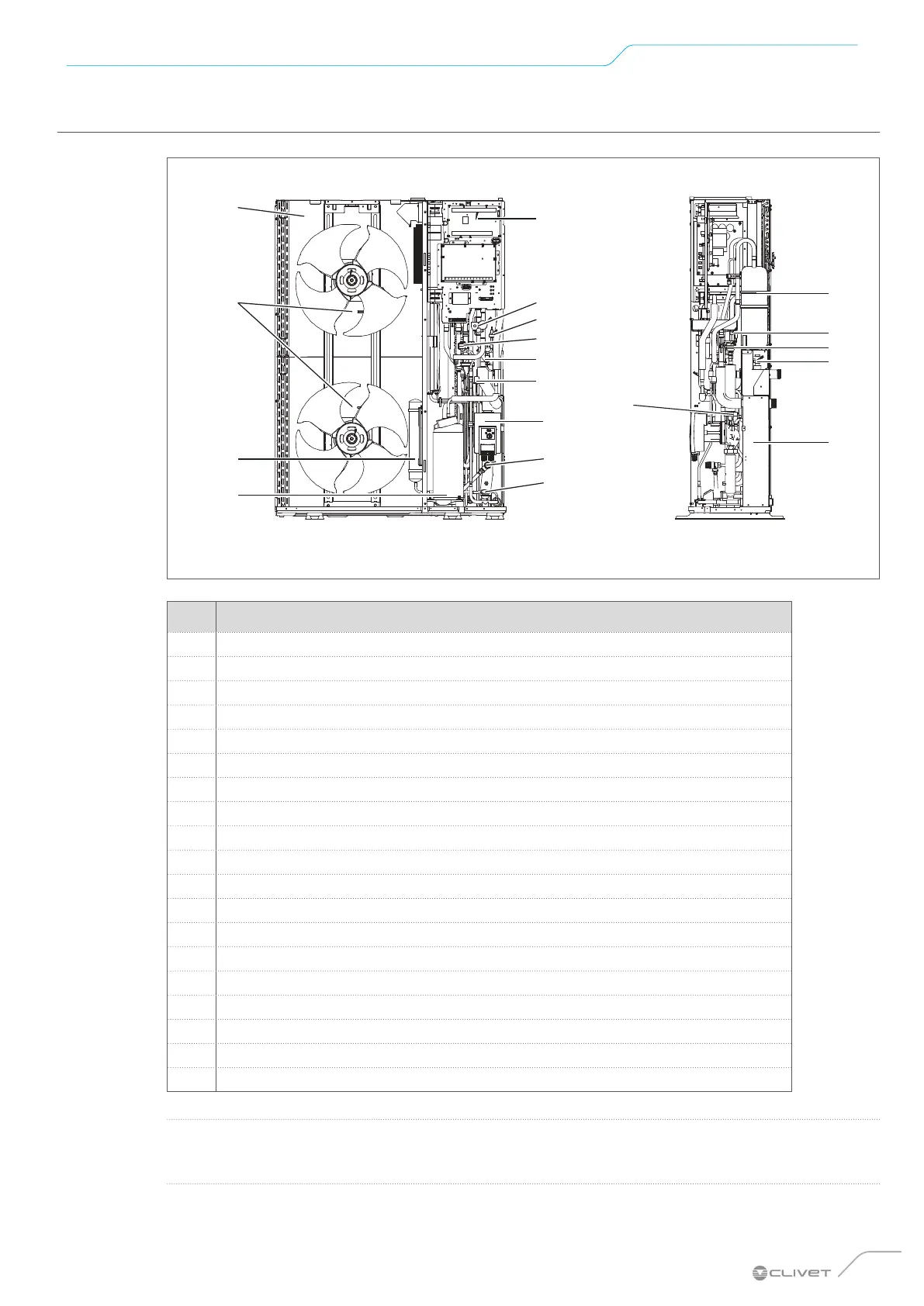
3.1.4 Sizes 9.1 to 14.1
13
1
2
3
4
5
6
7
8
9
10
11
12
14
15
16
17
18
19
Fig. 4
No. Component
1
Main board
2
4-way valve
3
Pressure sensor
4
Electronic expansion valve
5
HP pressure switch
6
LP pressure switch
7
Water circulator
8
Water pressure relief valve
9
Pressure gauge
10
Compressor inverter
11
Gas-liquid separator
12
Fan motor
13
Source exchanger: finned coil
14
Liquid receiver
15
Non-return valve
16
Air vent valve
17
Water flow switch
18
Water side heat exchanger
19
Expansion tank
O
WARNING
The pictures in this manual are provided for illustrative purposes only. The appearance of your appliance
may dier slightly from the illustrations shown here. Refer to the actual characteristics of the unit.
 Loading...