M01W45H6-06
WSAT-SC
75C-180F
- POSITIONING -
17
- POSITIONING -
GENERAL
For installing air-conditioning systems, it is necessary to consider the following:
• the technical spaces necessary for the machine and system
• the place where the machine will be installed
• the transport of thermal carrier fluids and relevant connections to the unit:
o water
o air
o refrigerant (unit in more sections)
• electrical connections
If these aspects are not evaluated carefully, they can affect the performances and the working life of the unit.
FUNCTIONAL CLEARANCES
When placing the unit, please respect the functional clearances indicated in DIMENSIONS section.
The functional spaces need to be observed because of the following:
• guarantee good operation of the unit
• to allow the performance of all maintenance operations
• protect the authorized operators and exposed people
If more units are placed close to one another, the functional spaces must be doubled.
POSITIONING
The units are designed for the installation:
• outdoor installations must be performed in fixed positions and in areas accessible only to qualified and
authorized personnel.
1. Install the unit raised from the ground
2. avoid installations in places subject to flooding
3. Consider the maximum level which can be reached by snow
4. Verify that the fixing/supporting points are level and suitable to support the weight of the unit (see the weight and the
weights distribution).
5. Put a rubber layer between the supporting plan and the unit to avoid noise and vibrations. It is recommended to put
the unit on specific anti-vibration devices (in this case, flexible joints are necessary on all the hydraulic/ aeraulic
connections – the joints are not supplied by Clivet).
6. Anchor the unit to the ground; foresee windbreak barriers in case of places where there are strong prevalent winds
The choice of where to position the unit is of fundamental importance for its use and working; therefore, there are things
to avoid:
• Obstacles to the air flow
• Difficulties of air circulation
• Leaves or other objects which can obstruct the exchange coils.
• Winds which contrast or favour too much air flow
• Phenomena’s of stratification or of air circulation
• Sources of heat in the nearby vicinity
• Positioning under the round level or near very high walls (evaluate with attention)
The previous situations cause working anomalies or stop the machine and cause:
• During SUMMER operation, increase of the condensation pressure with the decay of performances and possible
stops due to high pressure.
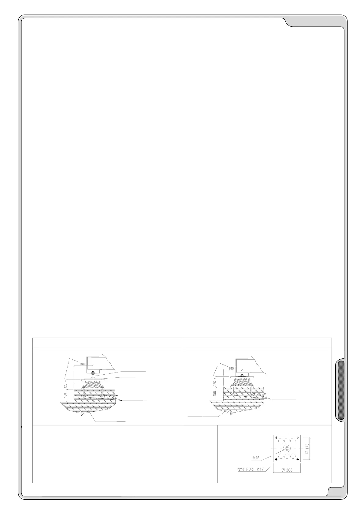
INSTALLATION OF ANTIVIBRATION MOUNTS
Use of an anti-vibration device requires the installation of flexible joints on the hydraulic / aeraulic / cooling connections.
With a jack for leveling the unit With a supported chassis
MINIMUM DIMENSIONS
SUGGESTED
CONCRETE FOUNDATION
JACK
PLATE
* UNLOADED HEIGHT
CLAMPS DROWNED IN THE
CONCRETE (NOT SUPPLIED)
MINIMUM DIMENSIONS
SUGGESTED
CLAMPS DROWNED IN THE
CONCRETE (NOT SUPPLIED)
* UNLOADED HEIGHT
* CONCRETE FOUNDATION
Each supporting point of the unit supports a different weight, so each anti-
vibration device is dimensioned for a specific supporting point and only on
this point can it be positioned.
The anti-vibration devices must be placed in accordance of the tables and
the dimensional drawings where the supporting points are shown by W1,
W2, W3 etc.
On each anti-vibration point, the relative identification code is printed , for
ex. C6100100.
 Loading...