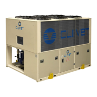
Do you have a question about the CLIVET WSAT-SC 90D Series and is the answer not in the manual?
General safety advice, manual purpose, and essential instructions for unit installation and operation.
Requirement for qualified personnel and adherence to local safety regulations for installation.
Guidelines for performing maintenance safely and ensuring repairs are done by authorized centers.
Unit must be used for its designed purpose, with additional safety measures for risk prevention.
Details on scroll compressor features like overload protection, oil heater, and anti-vibration mounts.
Components of the two independent refrigerant circuits, noting exceptions for specific models.
Components of the power and control sections of the electrical panel for unit management.
Section outlines risks beyond manufacturer's control and identifies danger areas around the unit.
Safety procedures for handling the unit and risks associated with incorrect installation.
Risks from burning smells, hot parts, unskilled repairs, and electrical hazards.
Risks from moving parts, refrigerant gas release, and contact with hot circuits.
Detailed safety information for R-407C refrigerant, covering identification, risks, first aid, and handling.
Overview of unit specifications, compressor, heat exchangers, fans, and electrical panel details.
Table detailing the operational limits for external and internal exchangers under various conditions.
Settings for high/low pressure switches, antifreeze protection, and safety valves.
Tables and graphs detailing operating pressures and pressure drops for internal exchangers.
Sound power and pressure levels for SC configuration at various operating conditions.
Sound power and pressure levels for EN configuration at various operating conditions.
Procedure for checking the unit for damage upon arrival and reporting issues within a specified timeframe.
Safety norms and considerations for handling the unit to prevent accidents and damage.
Illustrations and guidance on using correct lifting points and methods for safe unit handling.
Importance of functional clearances and guidelines for selecting an appropriate installation site.
Measures to prevent freezing, including glycol, heating cables, and system cleaning.
Installation of filter, flow switch, and handling of antifreeze solutions for evaporator connection.
Details on the modular pumping system and its versions for water capacity flow control.
Steps for safely connecting the unit to the main power supply, ensuring correct wiring.
Limiting absorbed electric power via an external signal for power input control.
Description of CLIVET TALK system modules (Interface, Central, Compressor, Evaporator) and their roles.
Essential checks before startup, covering installation, power, cleanliness, and system integrity.
Electrical system checks and procedure for crankcase heaters to prevent oil dilution.
Procedure for handling alarms, identifying causes, and resetting them safely.
Using refrigerant tables to test circuit operation by detecting parameters like pressure and temperature.
Identifying causes and troubleshooting steps for high-pressure conditions in the unit's refrigeration circuit.
Identifying causes and troubleshooting steps for low-pressure conditions in the unit's refrigeration circuit.


 Loading...