Do you have a question about the CLIVET WSAT-SC 75C Series and is the answer not in the manual?
Essential instructions, liability, storage, expert personnel, local safety regulations, power supply, packaging, maintenance, repairs, modifications, intended use, safety precautions, data updating.
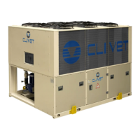
Details on compressors, structure, air/water exchangers, fans, refrigerant circuits, and electrical panels.
Lists available accessories and explains configuration code options like Energy Recovery, Low Temperature, Energy Savings, Acoustic Configuration, Energy Efficiency, and Heat Exchangers Approvals.
Details Clivet's commitment to quality management systems as per ISO 9001:2000 standards.
Explains CE mark compliance with relevant EC directives for product safety and electromagnetic compatibility.
Information on Clivet's participation in the Eurovent Certification Programme for Liquid Chilling Packages.
Covers danger areas, handling precautions, installation risks, general risks like burning smells, contact with hot parts, and maintenance by unskilled personnel.
Details risks associated with power supply lines, incorrect connections, and grounding, including electric shock and fire hazards.
Covers risks related to moving parts, refrigerants, water systems, and refrigerant safety charts for R-407C.
Detailed safety data for R-407C including exposure, properties, stability, toxicology, ecology, disposal, shipping, and regulations.
Details on acoustic configuration, cooling capacity, compressor, exchangers, fans, connections, dimensions, weights, and operating limits.
Information on compressor type, number, power, oil charge, refrigerant charge, and refrigerant circuits.
Provides detailed electrical and physical specifications for the 'EN' acoustic configuration across various unit sizes.
Details on cut-out devices, fouling correction factors, glycol use correction factors, and exchanger operating limits.
Provides sound power and pressure levels for SC and EN configurations under different power supply and ambient temperature conditions.
Procedures for checking the unit for damage and completeness upon arrival and reporting discrepancies.
Recommendations for proper storage conditions, including shelter, temperature, humidity, and handling of packaging.
Instructions for safe unit handling, considering weight, dimensions, critical points, and lifting points.
Details on 3-point and 4-point lifting, balancing the charge, and safely removing packaging material.
Essential factors for installing air-conditioning systems, including technical spaces, placement, and connections.
Requirements for functional spaces, general positioning guidelines, and factors to avoid for optimal placement.
Guidance on installing antivibration devices, including their placement and connection requirements.
Provides detailed dimensional drawings and measurements for 75C unit sizes, including weight distribution points.
Provides detailed dimensional drawings and measurements for 90C unit sizes, including weight distribution points.
Provides detailed dimensional drawings and measurements for 65D-100D unit sizes, including weight distribution points.
Provides detailed dimensional drawings and measurements for 110D-150F unit sizes, including weight distribution points.
Details water connection diagrams and dimensions specific to 165F-180F unit models.
Covers general warnings, intercepting valves, indicators, escape valves, leakage tests, insulation, supports, antivibration devices, freeze risks, emptying, and expansion tanks.
Details specific connections for the evaporator, including filter, flow switch, antifreeze, cleaning, and Victaulic joint procedures.
Illustrates a typical connection plan with a legend for various components and symbols.
Explains the modular pumping system (Hydropack) with different pump configurations (2, 2+1, 3) for capacity flow control.
Describes the function and types of recovery exchangers for condensation heat, including total and partial recovery.
Covers general electrical connection principles, power supply line details, signals/data lines, and electrical data tables for SC/EN configurations.
Details the procedure for connecting to the mains, functional connections, remote ON/OFF, signalization, second set-point, and demand limit.
Explains the configuration of optional external air temperature and humidity probes for set-point correction.
Details the optional Water Reset function and the composition of the CLIVET TALK modular system, including its various modules.
Describes various unit modules (Pump, Expansion Valve, Driver, Recovery) and communication interfaces (Remote Terminal, Modbus).
Explains the CLIVET TALK Local Network system for connecting multiple machines, including Master/Slave configuration and cable specifications.
Details the configuration and use of the Kit LonWorks gateway and CAN to Modbus conversion.
Covers essential checks before start-up, including unit installation, power supply, coils, ventilators, and preliminary cleaning.
Details start-up checks for aeraulic, refrigerant, water systems, electrical system, and crankcase heaters.
Covers verifying tensions, absorptions, scroll compressor rotation, remote inputs, set-point settings, water flow, and refrigerant circuit parameters.
Describes the control panel interface, unit ON/OFF operation, and thermoregulation principles.
Explains set-point compensations to protect compressors and adapt unit operation to installation characteristics.
Details set-point corrections, maintenance set points, demand limit, secondary set-point, and timetables for unit control.
Outlines the accessible parameter menu structure, lists key parameters, and explains keypad usage for setup and navigation.
Guides through setting parameters for Thermoregulation and configuring scheduling events (day, time, state, setpoint).
Details how to set the clock and date, and describes the structure for viewing unit status and module states.
Provides status information for general unit parameters and specific module data (Compressor, Evaporator).
Details unit status displays for compressor and evaporator modules, and provides instructions for managing alarms, pre-alarms, and viewing historical data.
Lists and describes alarm codes associated with the central module, including temperature, pressure, and system faults.
Details alarm codes related to Compressor, Pump, Recovery Expansion, and Evaporator modules, covering various faults and statuses.
Outlines preventive maintenance tasks for the unit's efficiency, breakdown prevention, and routine services on air coils, structure, and fans.
Details the recommended frequency and scope of maintenance inspections, including checks for power supply, electrical board, absorption, exchangers, filters, and refrigerant circuits.
Provides guidance on putting the unit at rest for long inactivity periods and presents refrigerant tables for overheating and subcooling calculations.
Contains detailed tables of pressure (Pg) and temperature (Ts, Td, Tb) values for refrigerants R22, R134a, R407C, and R410A.
Continues the detailed tables of saturation temperatures for various refrigerants across a range of pressures.
Guides on identifying and resolving issues related to faulty probes and pressure transducers.
Provides potential causes and checks for high pressure and low pressure conditions in the unit.
Addresses troubleshooting steps for compressor protections, fan protections, and pump protections.
Procedures for safely disconnecting the unit, including recovery of refrigerant and antifreeze fluids.
Guidelines for dismantling the unit and its components for disposal at authorized centers, emphasizing recycling and compliance with legislation.