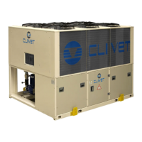
Do you have a question about the CLIVET WSAT-SC 150F Series and is the answer not in the manual?
Addresses potential risks from handling, installation, general hazards, and safety precautions.
Specific risks associated with the unit's electrical system, including wiring and grounding.
Discusses risks related to moving parts, refrigerant handling, and water system integrity.
Comprehensive data on refrigerant exposure, properties, toxicity, ecological impact, disposal, and shipping regulations.
Provides overall electrical specifications, cooling capacity, power inputs, EER, ESEER, and operating limits.
Essential considerations for unit placement, including technical spaces, functional clearances, and installation site selection.
Presents a summary of electrical data, including FLA, LRA, power input, and voltage unbalance.
Essential pre-start-up checks for aeraulic, refrigerant, water, electrical systems, and crankcase heaters.
Details operational checks, compressor rotation verification, and refrigerant circuit parameter monitoring.
Explains the thermoregulation process, including head step, scan time, and set-point compensation functions.
Discusses set-point corrections, demand limit function, and setting up daily operation schedules.
Details the accessible parameter menus, including thermoregulation, antifreeze, and evaporator settings, along with keypad usage.
Describes module-specific status, general alarm handling procedures, and how to view/reset alarms.
Outlines the structure of alarms and lists specific alarms for the central control module.
Details alarms related to compressor, pump, recovery, and evaporator modules for troubleshooting.
Guides on identifying and resolving issues related to faulty probes and pressure transducers.
| Cooling Capacity | 150 kW |
|---|---|
| Refrigerant | R410A |
| Compressor Type | Scroll |
| Power Supply | 400V/3Ph/50Hz |
| Weight | 1200 kg |
| Sound Pressure Level | 65 dB(A) |
| Water Flow Rate | 25.8 m3/h |


 Loading...