M01W45H6-06
WSAT-SC
75C-180F
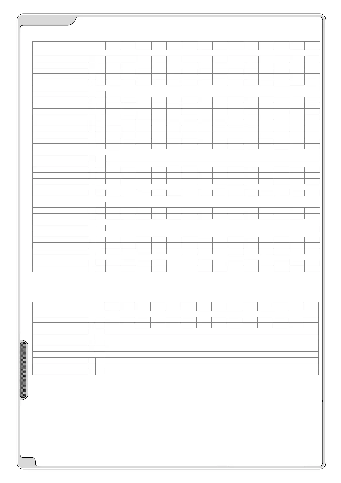
- ELECTRICAL DATA -
12
ACOUSTIC CONFIGURATION: (EN)
SIZES
65D 70D 75C 75D 80D 90C 90D 100D 110D 120D 135F 150F 165F 180F
COOLING
Cooling capacity 1 kW
173 185 187 196 206 233 225 253 296 319 354 385 416 440
Compressor power input
kW
55.7 60.8 71.9 67.7 73.8 88.7 81.9 92 98 111 122 135 153 171
Total power input
kW
61 66.1 75.8 73 79.1 93.8 87.2 97.3 106 118 131 146 164 182
EER
2.84 2.8 2.47 2.68 2.6 2.49 2.58 2.6 2.8 2.69 2.7 2.64 2.54 2.41
ESEER
4.26 4.2 3.83 4.02 3.9 3.86 3.87 3.89 4.2 4.04 4.2 4.1 3.95 3.75
COMPRESSOR
Type of compressors
SCROLL
No. of Compressors
Nr
4 4 3 4 4 3 4 4 4 4 6 6 6 6
Rated power (C1)
HP
30 35 75 35 40 90 45 50 55 60 60 75 75 90
Nominal Power (C2)
HP
35 35 - 40 40 - 45 50 55 60 75 75 90 90
Std Capacity control steps
Nr
4 4 3 4 4 3 4 4 4 4 6 6 6 6
Oil charge (C1)
l
12 14 18 14 16 18 16 16 19 24 24 24 24 24
Oil charge (C2)
l
14 14 - 16 16 - 16 16 24 24 24 24 24 24
Refrigerant charge (C1)
kg
27 30.5 25 30.5 34 25 36 38 40.5 51 51 57 57 57
Refrigerant charge (C2)
kg
30.5 30.5 - 34 34 - 36 38 51 51 57 57 57 57
Refrigerant circuits
Nr
2 2 1 2 2 1 2 2 2 2 2 2 2 2
INTERNAL EXCHANGER
Type of internal exchanger 2
PHE
No. of internal exchangers
Nr
1
Water flow rate
l/s
8.3 8.8 8.9 9.4 9.8 11.1 10.7 12.1 14.2 15.2 16.9 18.4 19.9 21
Pressure drop
kPa
30 34 26 30 33 29 34 34 35 40 31 39 37 41
Water content
l
17.2 17.2 19.7 19.7 19.7 21.4 21.4 23.9 29 29 37.4 37.4 42.5 42.5
EXTERNAL EXCHANGER
Front surface
m
2
11.9 11.9 7 11.9 11.9 8.3 11.9 11.9 17.3 17.3 17.3 17.3 17.3 17.3
EXTERNAL SECTION FANS
Type of fans 3 AX
Number of fans
Nr
4 4 3 4 4 4 4 4 6 6 7 8 8 8
Standard air flow
l/s
18200 17800 13900 17800 17800 15500 17800 16900 26550 26550 32500 35000 34200 33350
CONNECTIONS
Water fittings
3"
DIMENSIONS
Length
mm
2950 2950 3250 2950 2950 3650 2950 2950 4250 4250 4250 4250 4250 4250
Depth
mm
2195 2195 1095 2195 2195 1095 2195 2195 2195 2195 2195 2195 2195 2195
Height
mm
2250 2250 2030 2250 2250 2030 2250 2250 2250 2250 2250 2250 2250 2250
STANDARD UNIT WEIGHTS
Shipping weight
kg
2181 2260 1791 2325 2394 2137 2405 2418 2980 3129 3340 3453 3773 3875
Operating weight
kg
2197 2277 1811 2343 2413 2158 2426 2442 3005 3158 3373 3490 3810 3912
(1) data referred to the following conditions :
internal exchanger water = 12/7°C
room temperature = 35°C
(2) PHE = plates
(3) AX = axial-flow fan
OPERATING LIMITS
SIZES
75C 90C 65D 70D 75D 80D 90D 100D 110D 120D 135F 150F 165F 180F
EXTERNAL EXCHANGER
Max air intake temperature 1 °C
46 46 40 44 44 40 43 43 44 43 43 43 43 43
Max air intake temperature 2 °C
49 49 43 47 47 43 46 46 47 46 46 46 46 46
Min. air intake temperature 3 °C
-10
Min. air intake temperature 4 °C
-7
Min. air intake temperature 5 °C
3
Min. air intake temperature 6 °C
12
INTERNAL EXCHANGER
Max water inlet temperature
°C
22
Min. water outlet temperature 7 °C
6
Min. water outlet temperature 8 °C
-8
internal exchanger water = 12/7°C
difference between inlet / outlet water temperature = 5°C
Warning: the still air condition is meant as absence of air flow to
the unit. Any wind condition
can let air pass through the condenser coil thus worsening the
operating limits of the unit
(see limits with air speed at 0,5 m/s & 1 m/s).
Note: the Standard unit shall never be exposed, at temperatures
below -10°C while
supplied. On request it’s possible to take countermeasures for
the operation also in more
critical environmental conditions. For special conditions contact
our Sales Office.
ATTENTION: IN CASE OF PREDOMINANT WINDS,
WINDBREAK BARRIERS ARE NECESSARY.
(1) unit at full load
(2) Max inlet air temperature - capacity-controlled unit with standard limit device
(3) Min inlet air temperature - unit at full load and motionless ambient air
(4) Min inlet air temperature - unit at partial load and motionless ambient air
(5) Min inlet air temperature - unit at partial load and air speed of 0.5 m/s.
(6) Min inlet air temperature - unit at partial load and air speed of 1 m/s.
(7) standard unit
(8) B = Low Temperature.
 Loading...