36/50: Installation and Operation Manual 7
position, in this case the music source, microphone and music levels track the Zone 1
settings.
When setting the jumper(s) please ensure that you:
• Remove the mains cable from the rear of the product before removing the top panel.
•
Only reassemble the unit using bolts/screws identical to the original parts.
The Line 6 priority setting for the utility output also depends on the setting of the source
select jumper J10: in the Line 1 position Line 6 priority is not available. In both the Zone 1
source selection and Zone 1 Slave settings the Utility Line 6 priority is determined by the
Zone 1 Line 6 priority setting. If the microphone priority function is switched on, the music
signals will attenuate when an announcement is made.
17 Speaker Output Details
Plug in, two pole, screw terminal connectors are provided on the rear panel for the three
speaker outputs and these can accommodate flexible leads up to 2.5mm². Do not make any
connections to the unit with the power cable attached and please remember that it is good
practice to distance the output wiring from the input wiring and keep speaker cables twisted
until termination.
18 100V or 70V Line Operation
A three-channel line transformer module – the CXL-3120 is available as an accessory. This
gives the 36/50 up to three 100V or 70V, 40 watt outputs. This module is designed to fit
inside the mixer chassis and may be configured for 70 or 100V operation by means of wire
links on the PCB. Unless specified otherwise, the module is pre-configured for 100V output.
Each of the three output transformers on the module is connected to the main circuit board
by their own individual input cable. If a transformer output is not in use its input cable should
be disconnected from the main circuit board. When a transformer is in use the 65Hz high
pass filter for that transformers zone must
be activated by setting the appropriate jumper to
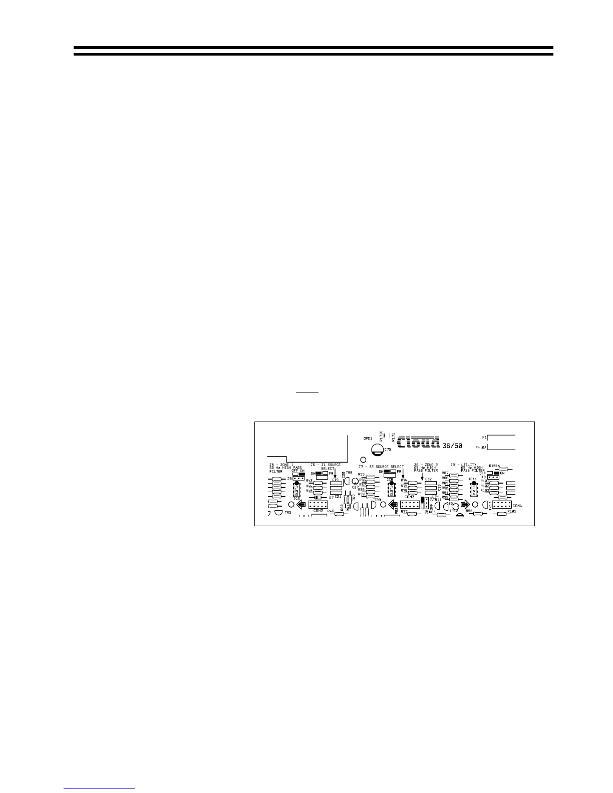
the ‘ON’ position. The jumpers are marked as follows:
Location of Jumpers J5, 8 & 9 (Inc Bose EQ Module Connectors)
J5 = Zone 1
J8 = Zone 2
J9 = Utility
If the filter is not switched
on, high input levels at
low frequencies may
result in the transformer
saturating and the
amplifier’s VI limiter
operating.
When setting the jumper(s) please ensure that you:
•
Remove the mains cable from the rear of the product before removing the top panel.
•
Only reassemble the unit using bolts/screws identical to the original parts.
19 Bose Speaker Equalisation Modules
Two speaker equalisation cards are available for the 36/50:
Model 8 card for use with Bose
model 8 speakers.
Model 32 card for use with Bose model 25, 32 and 102 speakers.
The internal Bose
equalisation module connectors (see diagram above) are marked on the
main PCB as: -
CON2 for Zone 1
CON3 for Zone 2
CON4 for the Utility Output
06/12/02 V5.0