BT-1 Installation Guide v1.0
10
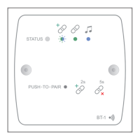
Connecting a BT-1F to an LM-2
If a BT-1F is being installed in a Zone which also contains an LM-2 Remote Input/Control Module, it should be connected to the
LM-2’s LINK connector instead of directly to the host unit, as shown below:
OUTPUT
LINK
Connect to
OUTPUT socket
Screened Cat 5
cable
HOST UNIT
(Z4 / Z8
MK4 OR 46/120 / 46/120MEDIA)
100 m max
Connect to
FACILITY PORT
Connect to
Output socket
Connect to
LINK socket
Screened Cat 5
cable
LM-2
BT-1F
If multiple LM-2s are “daisy-chained” in the Zone, the BT-1F should be connected to the LINK connector of the “last” LM-2 in
the chain. Note that as the BT-1F has no Link connector, it must always be the last module in a chain.
For details of how to congure a Facility Port to operate correctly with an LM-2 Remote Input/Control Module, please see the
LM-2 Installation Guide.
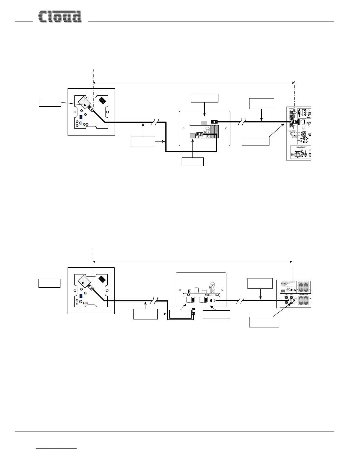
Connecting a BT-1E to an LE-1 or BE-1
If a BT-1E is being installed in a Zone which also contains an LE-1 or BE-1 Remote Input Module, it should be connected to the
LINK connector on the Remote Input Module instead of directly to the host unit, as shown below:
Connect to
OUTPUT socket
Screened Cat 5
cable
100 m max
Connect to
EXTENSION PORT
Connect to
Output socket
Connect to
LINK socket
Screened Cat 5
cable
BT-1E
LE-1
OUTPUT
LINK
LE-1 shown in example
If multiple LE-1/BE-1s are “daisy-chained” to an Extension Port, the BT-1E should be connected to the LINK connector of the
“last” LE-1/BE-1 in the chain. Note that as the BT-1E has no Link connector, it must always be the last module in a chain.
Note that it is not possible to connect a BT-1E to an ME-1 Microphone Input Module; ME-1 modules are connected to a DCM1’s
Microphone Inputs, not the Extension Ports.