7
Installation - connections
Connection to a Facility Port (BT-1F only)
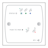
The BT-1 has two PCBs “piggy-backed” onto the rear of the faceplate. The RJ45 output connector (SK1) is located on the upper
PCB:
LOCATION OF REAR RJ45 CONNECTOR
(Sketch simplified; only primary components shown)
RJ45 OUTPUT
CONNECTOR
INSERT PLUG THIS
WAY, LATCH UPWARDS
SK1
RSL-6
3 2 1
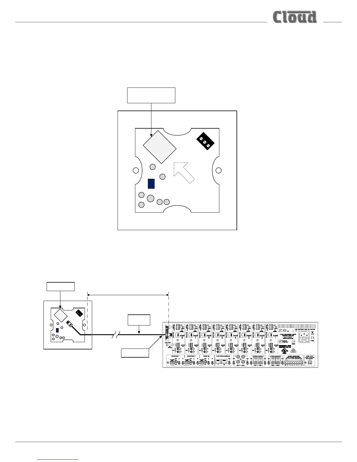
The output connector should be connected to the host unit’s FACILITY PORT for the Zone in which it is installed* with
screened Cat 5 cable and shielded RJ45 plugs.
Connect to SK1
Screened
Cat 5 cable
HOST UNIT (Z8MK4 illustrated)
100 m max
Connect to
FACILITY PORT
BT-1(UK version illustrated)
The maximum total Cat 5 cable length should not exceed 100 m. If further modules are being “linked” together (see “Connecting
a BT-1F to an LM-2” on page 10), this gure applies to the overall cable run from the host unit to the farthest module in the
chain.