2
GENERAL INFORMATION
SPECIFICATIONS
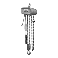
The Valustar Electric Chain Hoist is a highly versatile materials
handling device that can be used to lift loads that are within
rated capacity. The mechanical features of these hoists
include an alloy steel lift wheel, overload device (Protector),
hardened steel chain guides, simple two stage gear reduc-
tion, lifetime lubrication, forged steel hooks and lightweight
aluminum frames. The electrical features include hoist-duty
motor, magnetic reversing contactor, rugged control station,
heavy-duty motor brake and control transformer (3 phase
units). Hoists are supplied with a rigid upper hook suspension
as standard. Table 1 summarizes the hoist’s specifications.
CM REPAIR/REPLACEMENT POLICY
All Columbus McKinnon (CM) Valustar Electric Chain Hoists
are inspected and performance tested prior to shipment. If
any properly maintained hoist develops a performance prob-
lem, due to a material or workmanship defect, as verified by
CM, repair or replacement of the unit will be made to the
original purchaser without charge. This repair/replacement
policy applies only to Valustar Hoists installed, maintained
and operated as outlined in this manual, and specifically
excludes parts subject to normal wear, abuse, improper
installation, improper or inadequate maintenance, hostile
environmental effects and unauthorized repairs/modifications.
We reserve the right to change materials or design if, in our
opinion, such changes will improve our product. Abuse,
repair by an unauthorized person, or use of non-CM replace-
ment parts voids the guarantee and could lead to dangerous
operation. For full Terms of Sale, see Sales Order
Acknowledgement. Also, refer to the back cover for
Limitations of Warranties, Remedies and Damages, and
Indemnification and Safe Operation.
Valustar Electric Chain Hoist Specifications
DC MAX. CAP. LIFTING SPEED MOTOR MIN. HOOK POWER SUPPLY NET WEIGHT
CODE CODE MODEL (TONS) F.P.M. H.P. DISTANCE VOLTS/PHASE/HERTZ (POUNDS)
2401 62401 WB 1/4 16 1/4 16-1/2" 115-1-60 51
2402 62402 WB 1/4 16 1/4 16-1/2" 230/460-3-60 61
2413 62413 WE 1/2 8 1/4 19-7/8" 230/460-3-60 72
2412 62412 WE 1/2 8 1/4 19-7/8" 115-1-60 62
2403 62403 WF 1/2 16 1/2 16-1/2" 115-1-60 53
2404 62404 WF 1/2 16 1/2 16-1/2" 230/460-3-60 68
2405 62405 WH 181/2 19-7/8" 115-1-60 69
2406 62406 WH 181/2 19-7/8" 230/460-3-60 78
2414 62414 WJ 1/2 32 1 17-5/8" 230/460-3-60 105
2407 62407 WL 1 16 1 17-5/8" 115-1-60 109
2408 62408 WL 1 16 1 17-5/8" 230/460-3-60 106
2409 62409 WR 28124-1/2" 115-1-60 129
2410 62410 WR 28124-1/2" 230/460-3-60 126
Series 635 Low Headroom Trolley Specifications
MAX. CAP. TREAD DIA. OF MIN. RADIUS
(TONS) FOR USE WITH MODELS ADJUSTABLE FOR S-BEAMS WHEELS (IN.) CURVE (IN.)
1/4 to 1 WB, WE, WF, WH, WJ, WL 4" X 7.7# TO 15" X 50# 3-1/8 24
2 WR 6" X 12.5# TO 18" X 54.7# 4-3/4 24
Series 635 Motor-Driven Trolley Specifications
MAX. CAP. POWER TRAVEL MOTOR ADJUSTABLE MIN. RADIUS
(TONS) FOR USE WITH MODELS SUPPLY SPEED (FPM) H.P. FOR S-BEAMS CURVE (IN.)
1/4 to 2 WB, WE, WF, WH, WJ, 115-1-60 75 1/4 6" x 12.5" 30
WL, WR 230-3-60 thru
or 460-3-60 15" x 50#
Table 1
For more information contact: Sievert Crane and Hoist, (708) 771-1600, parts@sievertelectric.com, www.sievertcrane.com