AN241
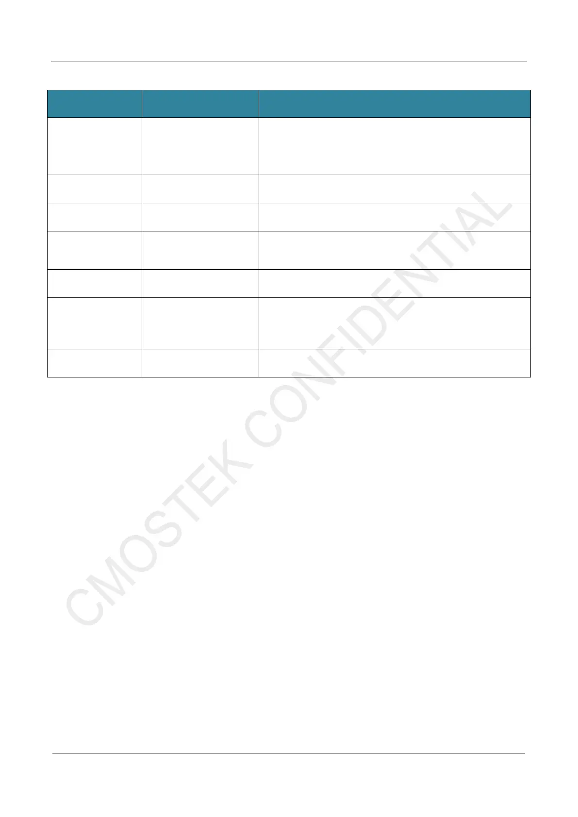
Table 1-1. CMT2310A-EM Description
No. Function Description
1 DC-DC Select
CMT2310A has an embedded DC-DC module. You can select the DC-
DC mode or disable it. Noted that this jumper is a hardware choice and
needs to combine with the control software. If you want to enable the
DC-DC module, the software also needs to configure the
corresponding register BUCK_SEL to 1 (located in Page1, address
2 Current Detect
The power consumption of CMT2310A in each working state can be
determined by connecting the current test jumper to the ammeter.
3 Test Pin Test points of each pin of CMT2310A
4 GPIOn Select
R2-R5 is corresponding to GPIO2-GPIO5 and the 0R resistor is used
as selection of GPIOn according to GPIO2-GPIO5. If the factory default
is R4, that is, select the GPIO4 as GPIOn.
Note: Only supported by Ver003, not compatible with old versions.
5 EM Version Information The current CMT2310A-EM version information is Ver003.
6 Crystal
:
The X1 is patched with crystal;
The X2 patch position crystal is TCXO, and the TCXO power supply is
provided by the NIRQ pin of the CMT2310A.
:
Only supported by Ver003, not compatible with old versions.
7 EM Connector
The 10 pins connector of CMT2310A-EM is defined as shown in the
figure.
Note
:
1. For more information of CMT2310A-EM, please refer to its schematic diagram - CMT2310A-EM revXXX SCH.pdf
2. Since this firmware requires GPIO4, make sure that on CMT2310A-EM, GPIOn selects GPIO4, that is, R4 is patched with
0R.
 Loading...