AN241
Figure 2-2. Startup Interface(not inserted CMT2310A-EM)
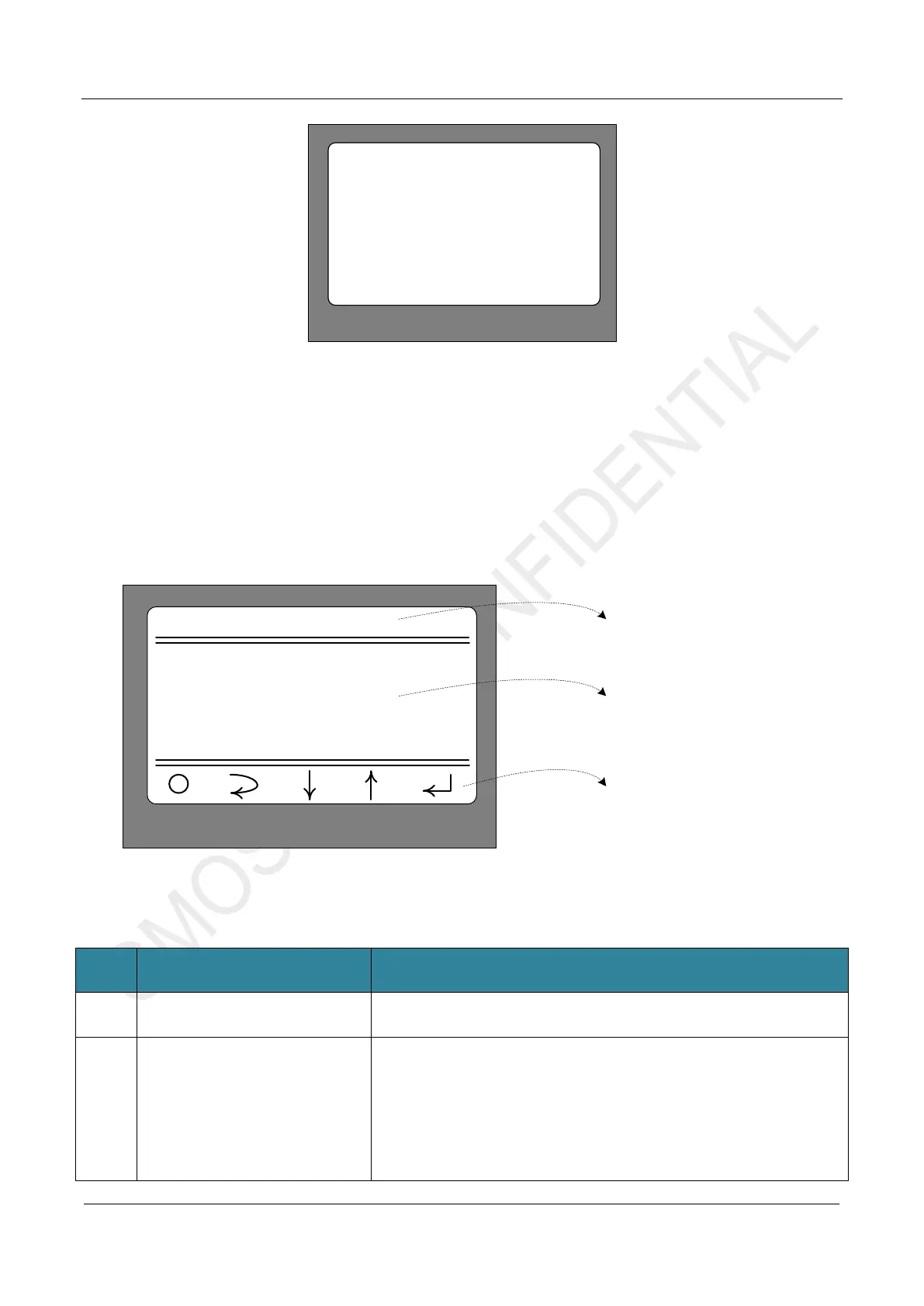
2.2 Main Menu
After the screen is powered on for about 1 second, the screen will switch to the normal menu mode, as shown
in Figure 2-3 below. (If the CMT2310A-EM is not inserted properly or the CMT2310A chip cannot be identified,
the screen will remain in the display state as shown in Figure 2-2 until CMT2310A-EM is inserted properly or
CMT2310A can be recognized normally.)
CMT2310A EB GUI
1 Modulation
2 Work Mode
3 Frequencry Band
4 Data Rate
2. Submenu selection
area
1. Title
3. Corresponding
key function area
Figure 2-3. Main Menu Interface
No. Function Description
1 Title area CMT2310A EB GUI
2 Submenu selection area
13 submenu selections are shown in the area
1. Modulation(Modulation and demodulation mode selection)
2. Work Mode(Working mode selection)
3. Frequencry Band(Frequency band selection)
4. Data Rate(Rate/frequency offset parameter selection)
5. Tx Output Power(Transmission power selection)
6. Preamble Length(Preamble length selection)
(
)