AN241
1 Hardware Platform Introduction
The CMT2310A evaluation board hardware test platform is composed of CMT2310A-EB and CMT2310A-EM:
CMT2310A-EB is the test panel of the evaluation board, using HC32L136 as the development board
of the CMT2310A module, factory set with CMT2310A function and performance evaluation firmware,
and can also be used as the CMT2310A development board.
CMT2310A-EM is the evaluation module, and the module is affixed according to the matching
parameters of the target frequency band (2 common frequency bands are provided: 434MHz and
868MHz with transmission power of +20dBm Direct Tie hardware matching mode), which can be
used by users for evaluation before scheme selection or reference comparison in design.
CMT2310A-EM also supports to connect to the RFPDK upper computer interface software through
USB Programmer and realizes online control of the CMT2310A functional testing and verification.
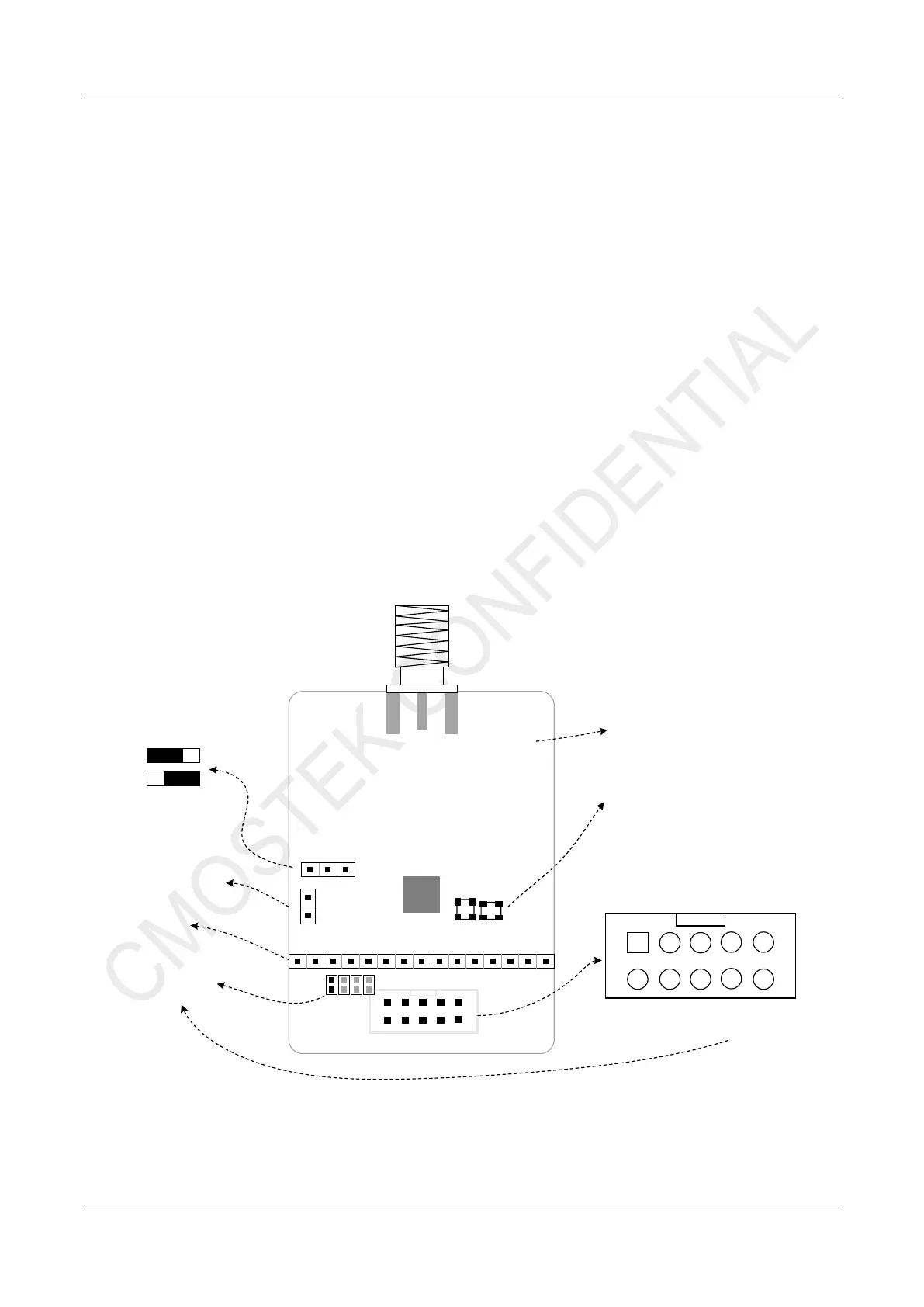
1.1 CMT2310A-EM Introduction
The following figure shows the top view and introduction of CMT2310A-EM
GND
R4
R5
R3
VDD
VCC
R2
VDD_PA
GPIO3
GPIO5
GPIO4
VIN
GPIO2
SCLK
SDO
SDI
NC
CSB
NC
NIRQ
GPIO1
GPIO0
CMT2310A
X1
X2
CMOSTEK
CMT2310A-EM
Rev xxx
Direct Tie
1. DC-DC Select
OFF
ON
2. Current Detect
3. Test Pin
4. GPIO2~GPIO5
Connect Select
6. Crystal
X1: for Passive Crystal OSC.
X2: for TCXO
5. EM Version Information
12
34
56
78
9
GND
VCC
SDO
SDI
10
NIRQ
GPIOn
GPIO0
GPIO1
SCLK
CSB
7. EM Connector
Figure 1-1. CMT2310A-EM Introduction
 Loading...