AN241
1.2 CMT2310A-EB Introduction
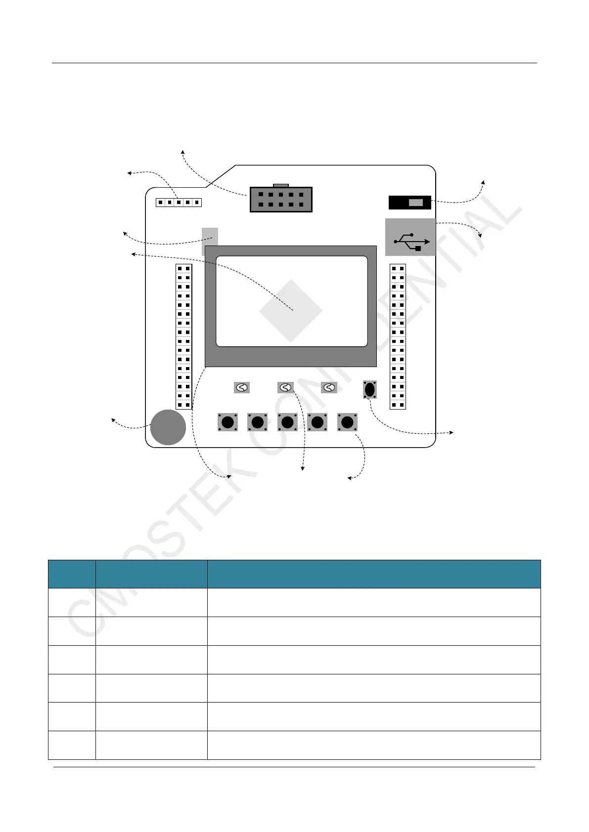
The following figure shows the top view and introduction of CMT2310A-EM
VDD
CMOSTEK
K1 K2 K3
CMOSTEK
SW 20220712 FW C0
K4 K5
LED1 LED2 LED3
RST
RF-EB Rev-003
Power On/Off
USB TypeB
GND
PB11 PB10
PB02 PB01
PB00 PC05
PC04 PA07
PA06 PA05
PA04 PD05
PD04 PA03
PA02 PA01
PA00 AV DD
GND PC03
PC02 PC01
PC00 RSTB
GND GND
GND GND
PC13 VCAP
PB12 PB13
PB14 PB15
PC06 PC07
PC08 PC09
PA08 PA09
PA10 PA11
PA12 PA13
PD06 PD07
PA14 PA15
PC10 PC11
PC12 PD02
PB03 PB04
PB05 PB06
PB07 BOOT
PB08 PB09
GND VDD
4. HC32L136
EB Main Contorller
2. J-Link Debug
Interface
1. CMT2310A-EM
Connector
GND
SWCLK
SWDIO
VDD
RSTB
3. CH340G
USB to UART Interface
8. USB TypeB Connector
9. Power Switch
7. Reset Key
5. Buzzer
6. User Interface (LCD, LED, Key)
Figure 1-2. CMT2310A-EB Introduction
Table 1-2. CMT2310A-EB Description
No. Function Description
1 CMT2310A-EM Connector
Connect the 10PIN base of CMT2310A-EM and connect the HC32L136 control pin as
shown in the table below
2 J-link Debug Interface
J-link debug interface(SWD)
3
CH340G
USB to UART Interface
CH340G USB to UART interface chip (HC32L136 controller PB06 is TxD, PB07 is
RxD)
4
HC32L136
EB Main Controller
Eb board main controller HC32L136。
5 Buzzer Direct beeper on EB board
6 User Interface
EB board operation interface:
1. LCD display(128x64 lattice);
 Loading...