AN241
No. Function Description
2. LED1~LED3 status indicator
;
3. K1~K5 operation key;
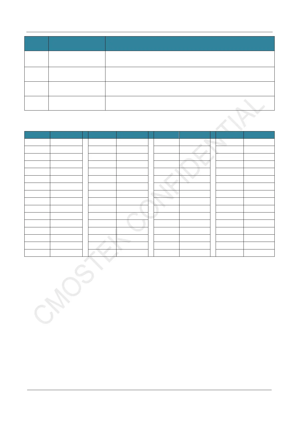
Specific connection control pins of HC32L136 are shown in the table below
7 Reset Key HC32L136 reset control key
8 USB TypeB Connector USB B connector, can supply power to EB via the USB
9 Power Switch Switching the EB board is power from USB or battery (AA dry battery X3).
Table 1-3. CMT2310A-EB Pin Function of the Main Controller HC32L136
PB12 LCD_CS
PB13 LCD_RST
VDD --
GND --
PB14 LCD_RS PB15 LCD_SDA PB11 -- PB10 --
PC06 LCD_SCK PC07 LCD_LED PB02 RF_NIRQ PB01 RF_GPIO1
PC08 -- PC09 -- PB00 RF_GPIO0 PC05 --
PA08 -- PA09 -- PC04 RF_GPIOn PA07 RF_SDI
PA10 -- PA11 -- PA06 RF_SDO PA05 RF_SCLK
PA12 -- PA13 SWCLK PA04 RF_CSB PD05 --
PD06 -- PD07 -- PD04 -- PA03 --
PA14 SWDIO PA15 -- PA02 -- PA01 --
PC10 LED3 PC11 LED2 PA00 -- AVDD
PC12 LED1 PD02 Buzzer GND PC03 --
PB03 K5 PB04 K4 PC02 -- PC01 --
PB05 K3 PB06 UART_TxD PC00 -- RSTB RST_KEY
PB07 UART_RxD BOOT -- GND -- GND --
PB08 K2 PB09 K1 GND -- GND --
GND -- VDD -- PC13 -- VCAP --
Note
:
1. For more information of CMT2310A-EB, please refer to its schematic diagram - CMT-RF_EB revXXX
SCH.pdf
In summary, CMT2310A-EB can be regarded as a development board with HC32L136 as the main control,
which provides a variety of user-computer interaction interfaces (LCD lattice, beeper, LED, keys, USB-to-
UART bridge, etc.). Meanwhile, CMT2310A-EM is equipped with a 10 PIN master socket, which is very
suitable for function familiarization, debugging, verification and testing of CMT2310A.


 To Next Page