Need help? c-m-p.com/support 13
4A. SYSTEM ELECTROMECHANICAL OVERVIEW
CAUTION
Disconnect power before performing service. Refer to the IMPORTANT SAFETY INSTRUCTIONS displayed
in the front of this manual.
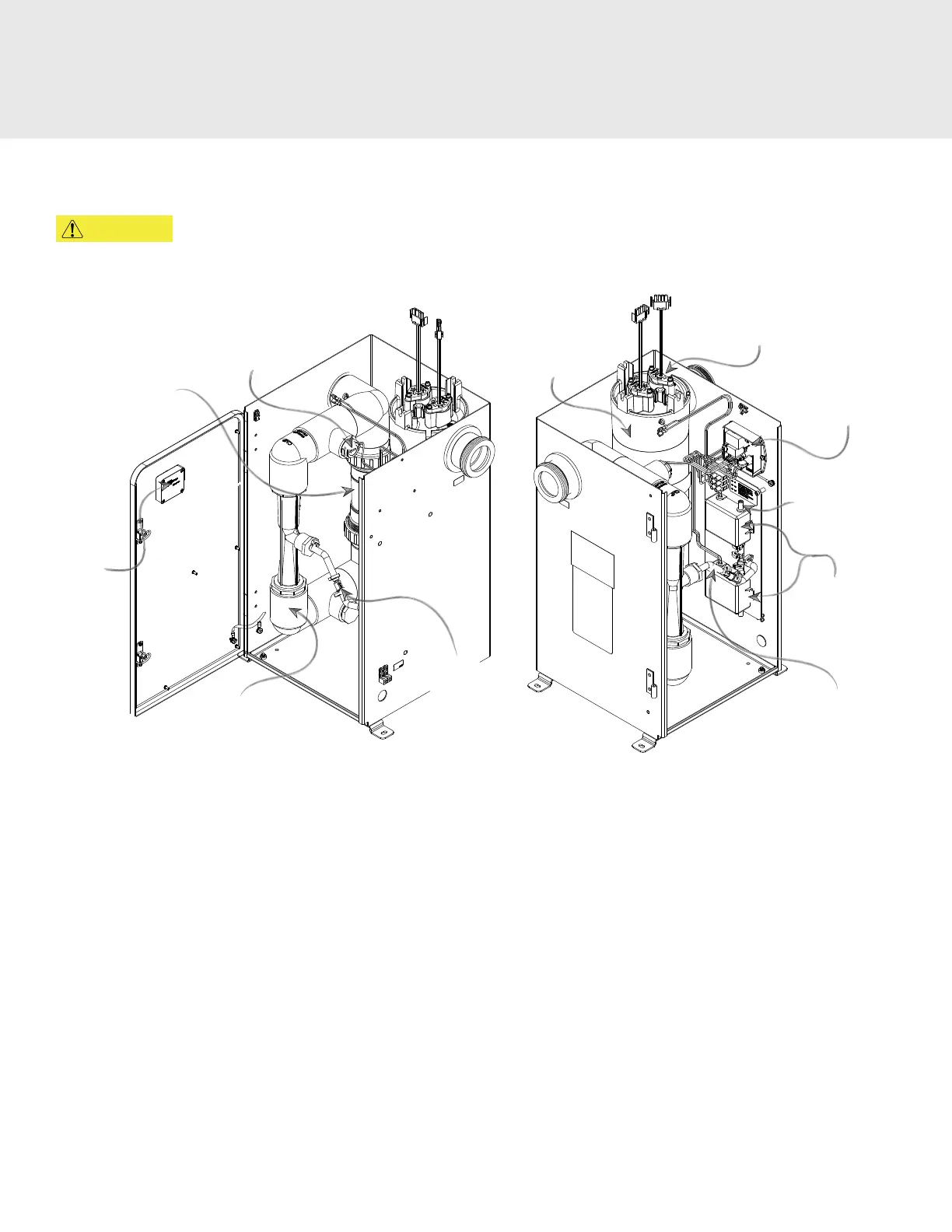
UV-C
Reactor
Flow
Switch
Variable
Speed
Check Valve
Smart
Status
Reset
Injector
Manifold
Power
PCB Board
APG2
Air Filter
APG2
Ozone
Modules*
Ozone
Gas Line
UV-C Lamp
Ozone
Check
Valve
Figure 10: DEL AOP Electro-Mechanical Overview
(AOP 40 Shown)
4A-1. Ozone Module Description
*The DEL AOP is constructed with one (AOP 25) or two (AOP 40) APG2 corona discharge ozone modules. Blue ozone light on
system smart status LEDs indicate ozone modules are operating properly (refer to Figure 8 for a more detailed view).
4A-2. Injector Manifold Description
Water owing through the injector manifold generates the vacuum that draws ozone into the water. The spring-loaded valve
automatically adjusts for various water ow rates to keep the DEL AOP operating over a wide range of conditions.
4A-3. Ozone Gas Line Description
Gas from the ozone modules is drawn through the ozone gas Line by the injector and into the water. The ozone check valve
(refer to Figure 12) in this line prevents water from migrating back to the ozone modules when the DEL AOP is not running.
4A-4. Ozone Module Air Filter Description
The air entering the ozone modules passes through the air lter (refer to Figure 11) on each module inlet. The lter is held in
place by the rubber lter cap.
4. MAINTENANCE & SERVICE