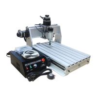
This document serves as a user guide for a three-axis CNC engraving machine, specifically models 3020Z-DQ and 3040Z-DQ. It provides comprehensive instructions for installation, operation, and maintenance, aiming to help users master the device quickly and efficiently.
The primary function of this machine is surface engraving on various materials. It is designed for plastics, bamboo, timber, and non-ferrous soft metals. The guide emphasizes that using the machine for other purposes may cause damage. It operates by translating design software outputs (G-code, nc, or Tab files) into physical movements of a cutter, allowing for precise and detailed engravings. The machine's workflow involves software installation and parameter settings, design and G-code output, workpiece clamping, and finally, the engraving process itself.
Usage Features:
The engraving machine is a mechatronics processing tool, requiring operators to have a grasp of relevant professional knowledge. The guide outlines a basic workflow for using the machine, starting with software setup.
-
Software Installation and Settings:
- Users are instructed to install "control software Mach3" on a desktop computer. Mach3 is recommended, though EMC2 and Kcam4 can also be applied.
- Parameters for the control software must be set according to the engraving machine's requirements.
- The computer used must have parallel ports; notebook PCs or USB parallel ports are not suitable. Minimum computer specifications include a CPU/1G, 512M memory, 20G hard disk, a mainboard with a parallel port, and the WIN-XP operating system.
- Design software like ARTCAM, PowerMill, and TYPE are commonly used for creating engraving content. The guide clarifies that the software is not included with the machine and users should purchase it from official websites.
- A critical step after installing Mach3 is to reboot the computer immediately before opening the software for settings. Two specific files must be copied to the installation directory and replace the original files.
- Detailed instructions with screenshots are provided for configuring Mach3 parameters, including port and pin settings for encoders, spindle setup, motor outputs, input signals, and output signals. Specific pin numbers and settings for X, Y, Z, A, B axes, and spindle are outlined. Motor tuning settings, including velocity and acceleration profiles, are also detailed.
- Spindle pulley settings are also part of the configuration process, ensuring the machine operates within specified speed ranges.
-
Trial Run and Manual Control Test:
- Before operation, users must verify correct connections between the computer, control box, and engraving machine, as well as proper software installation and parameter settings.
- A manual test involves checking the step motors. Without power, the handwheels should turn easily. Once power is supplied and the "POWER" switch is on, the motors should self-lock, making the handwheels slightly tighter to turn. This indicates the machine is ready for control.
- Starting Mach3 software, users should click the "RESET" button if it's flashing to ensure it's static before operation.
- The guide explains how to use keyboard direction keys (X, Y, Z axes) and the Mach3 manual control panel (accessed via the "Tab" key) to test axis movement. Any abnormal movement requires contacting the dealer.
-
Triaxial Coordinate Definition:
- A reference drawing of the triaxial coordinate definition is provided. If axis running directions are incorrect during the trial run, users can adjust the "Dir LowActive" setting in Mach3's "Motor Outputs." This coordinate definition is a standard mode but can be customized based on user habits and design software requirements.
-
Primary Engraving Practice:
- This section guides users through their first engraving task using a simple graphic and text example.
- Step one: Clamp materials. Materials must be fixed securely on the operating platform using clamps. The guide includes diagrams illustrating how to use high-level screws, clamping screws, and clamping plates.
- Step two: Tool setting. This involves moving the cutter to the initial position on the material surface. For beginners, it's recommended to set the initial point at the center of the material, specifically at the intersection of diagonal lines.
- Step three: Lead in tool path code. Users import G-code (e.g., "shidiao-1.cn" from the provided CD) into Mach3.
- Step four: Begin to engrave.
- First, "Zero X, Zero Y, Zero Z" must be clicked to reset axial coordinates.
- Then, the "POWER" switch on the electrical cabinet and the "SPINDLE" switch are turned on. The spindle motor should start moving clockwise.
- The speed adjustment button on the electrical cabinet is slowly turned clockwise to reach maximal speed (around 11000 cycles).
- Finally, clicking "Cycle Start" in Mach3 initiates the engraving process.
- Safety Attention: During engraving, hands should be kept away from the high-speed cutter. After engraving, the spindle speed should be reduced to minimum, the Z-axis raised, the spindle motor moved away from the material, and the power switch turned off. Scraps must be cleared promptly.
- Key Points for Engraving: Leave sufficient margin when clamping materials to avoid cutter contact with screws, reset triaxial coordinates after tool setting, and adjust the spindle speed adjustment button to the zero position anticlockwise.
-
Auxiliary Operating Platform:
- An auxiliary operating platform is a sacrificial board (e.g., PVC, PMMA, or wood) installed on the machine's original platform. Its purpose is to prevent damage to the original platform during cutting operations, especially when cutting through materials.
- Installing it involves fixing a soft board and then milling its surface with the engraving machine to achieve high flatness. This is particularly useful for materials requiring high flatness, such as double-color plates or PCBs. For smaller objects, the auxiliary platform can be installed on a part of the machine and left in place.
-
Secondary Engraving Practice:
- This section demonstrates engraving on a double-color plate using the auxiliary operating platform.
- Steps include sticking double-faced adhesive tape to the back of the plate, pasting it onto the milled auxiliary platform, tool setting, beginning engraving, and displaying the finished product. An example file "shuangseban.nc" (75x85mm) is provided on the CD, with its initial point at the top left corner.
-
Application of Tool Setting Gauge:
- The tool setting gauge is an auxiliary tool for Z-axis tool setting, supported by Mach3 R2.63.
- Attention: Before use, the gauge's accurate thickness must be measured with a vernier caliper and input into the "PROBE-H" character box in Mach3 (e.g., 20mm), then saved by pressing "Enter."
- Important: Before each use, touch the tool setting gauge surface with the clamp on the red cable to check if the indicator light on the tool setting interface turns red. If not, check the cable connection or if the software was reinstalled without proper setting.
- Using Method: Place the gauge on the material, manually adjust the Z-axis so the tool tip is no more than 20mm from the gauge surface (as the automatic bottom detection distance is 20mm). Clip the tool shank with the red cable's clamp. Turn on the control box's "POWER" switch, click "Tool Setting" in Mach3. The Z-axis will slowly decline, stop upon touching the gauge, and automatically return 5mm upward. Remove the gauge; tool setting is complete. The Z-axis coordinate data will not be zero.
-
Control the Spindle Motor through Software:
- The machine supports Mach3 for spindle motor start, stop, and speed regulation. Users can also embed M03 (start forward rotation) and M05 (stop/restore minimum speed) codes in engraving programs for automatic control.
- Method:
- Set the control box switch to "M" (Mach3 control). "H" is for manual control. The "SPINDLE" switch must be on regardless of the method.
- Turn on the "SPINDLE" switch on the control box.
- In Mach3, click the "Spindle Speed" character box, input 11000, and press "Enter."
- Click "Spindle CW F5" to start the spindle at high speed. The green bar can be dragged to adjust speed. Clicking "Spindle CW F5" again stops it.
- The "SPINDLE.txt" file on the CD provides detailed information and examples for M03 and M05 codes.
Maintenance Features:
Regular maintenance is crucial for the machine's longevity and performance.
- Post-Engraving Cleaning: After each engraving session, turn off the principal axis and power switch, then clean all generated scraps.
- Monthly Lubrication: Once a month, lubricate the guide ways, bearings, and screw mandrels. Use clean cotton fabric with white oil (sewing-machine oil) to clean the guide ways, then apply white lubricating grease to the screw mandrels. Operate the machine several times, then re-lubricate all parts. Avoid consistent grease application.
- Drag Chain Cable Inspection: At least once a month, check the cable lines in the drag chain. Loosen any tight cables to ensure they are all loose. Tight cables can lead to broken internal copper wires due to repeated flexure, causing poor contact and potential motor control issues.
- Screw Tightness Check: Monthly, check all screws and tighten any that are loose.
- Spindle Motor Replacement: The spindle motor is a consumable part. If abnormal sounds or foreign smells occur during use, it indicates a need for replacement. It should also be replaced after 600 hours of regular use to maintain good engraving performance.
- Long-Term Storage: If the machine will not be used for an extended period, oil it for maintenance and store it in a dry place covered with plastic film.