Connect to Power
Your factory trained COATS
®
Service Technician should do the
final check to verify the power installation before connecting the
balancer to a power supply. Failure due to improper power con-
nection will void the warranty.
Connect the balancer to an appropriate electrical receptacle.
Refer to Figures 4 and 5, as well as Electrical Requirements on
page 1.
Note: If pedestrian or equipment traffic might damage the
standard power cord, power outlets must be enclosed in a race-
way on the floor or in an overhead drop.
Note: Electric outlets must be solidly connected. There should
be less than 1 Ω electrical resistance between the ground pin
and earth ground. The installer or electrical inspector must ver-
ify the outlet installation before connecting the balancer. Failure
due to improper power connection will void the warranty.
Note: The green wire in the cord is the grounding wire. Never
connect the green wire to a live terminal.
Initial Testing
This should be performed by your factory trained COATS
®
Service Technician.
Precautions: Initial testing should be performed by the
instructor. Power requirements must be verified by the installer
or instructor before connecting balancer. Failure to observe this
precaution may void warranty.
Power: Plug power cable into power outlet receptacle. Set cir-
cuit breaker in building breaker panel on. Set On/Off switch on.
Leave power on during an entire work day.
Cooling Air: Check to verify cooling air blower is running. Do
not operate unit unless cooling air flow is present.
*Spin: (220 VAC 3 phase units) Press START button with hood
down. Faceplate should rotate clockwise. If initial direction of
faceplate rotation is incorrect, an error message will show in the
control panel display: ERROR. Set On/Off switch off. Set build-
ing circuit breaker off. Interchange X and Y wires in outlet plug.
Set building circuit breaker on. Set On/Off switch on. Press
TRUCK button. Faceplate initial rotation should be clockwise.
*Spin: (220 VAC single phase units) Press START button with
hood down. Faceplate should rotate clockwise for an interval
and then stop.
Note: If the above conditions cannot be obtained during initial
test, call the distributor for service advice.
*Mount a tire/wheel assembly to avoid HUB ERR.
Direct Drive
COATS 6401 Truck Wheel Balancer • 5
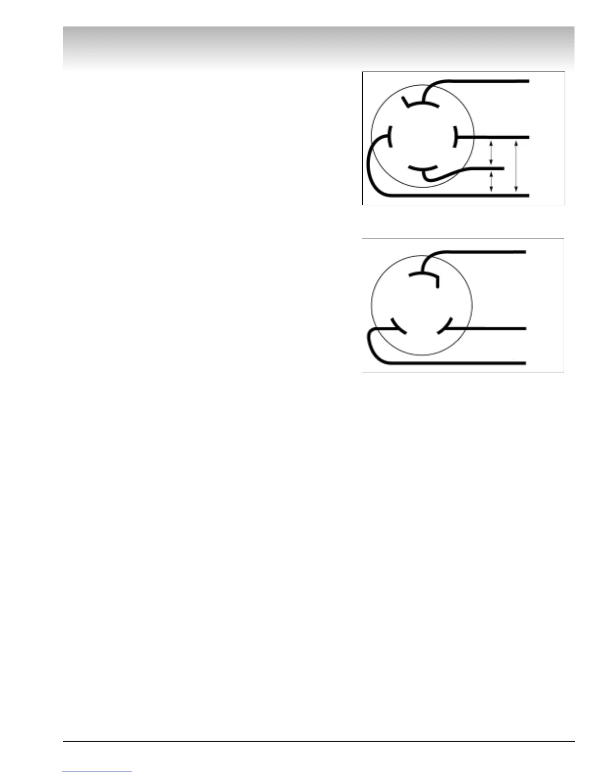
Figure 4 - Three-Phase Wiring Diagram
Figure 5 - Single-Phase Wiring Diagram
Three-Phase
Ground
Hot
195-230 V
Between
Hot Wires
Hot
Hot
Single-Phase
A – Red
B – Black
Green/
Ground