10 • Important: Always read and follow the operating instructions.
Inflation
Tire inflation is performed in three steps: BEAD
SEAL, BEAD SEAT, and INFLATION. These steps are
explained in detail on page 14. Read the explanation of
each step and understand them thoroughly before pro-
ceeding.
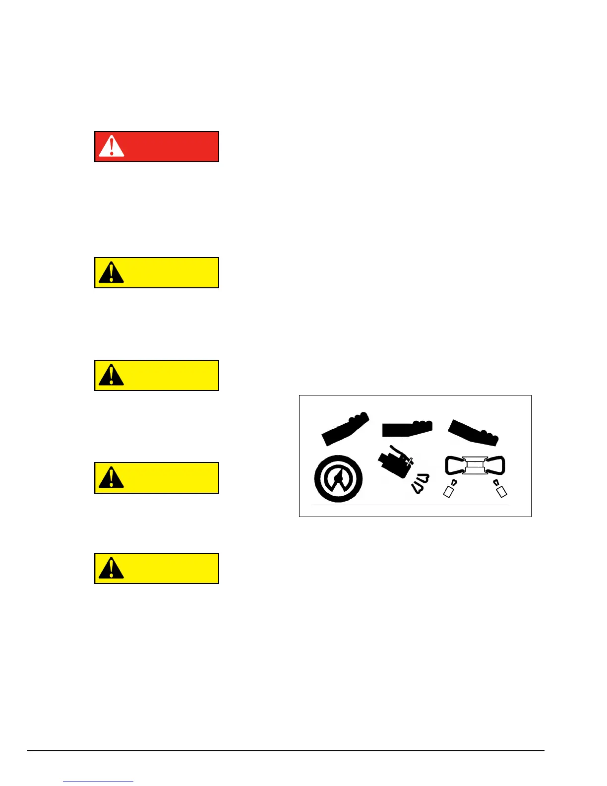
Tire failure under pressure is hazardous. This
tire changer Will Not Restrain Exploding
Tires, rims or other related equipment.
Inspect tire and wheel carefully for match,
wear, damage, or defects before mounting.
Always use approved tire bead lubricant
during mounting and inflation.
The clip-on chuck allows the operator to
keep hands and entire body back from
inflating tire. The chuck must be an
open/freeflow style with all parts in proper
working order.
Check for proper inflation gauge operation.
Accurate pressure readings are important to
safe tire inflation. Refer to the Operating
Maintenance section of this manual for
instructions.
If the rim has been clamped from the out-
side for tire mounting, release the clamps,
lift the tire, and move the clamps to the cen-
ter of the table top.
If the wheel/tire has a diameter larger than
14-inches and is difficult to bead seal, the
clamps should be moved to the center of
the table top for the bead seal operation.
The inflation pedal, located at the rear of the left side
of the machine, controls the flow of air through the
inflation hose, and has three positions.
Note:The clip-on chuck on the end of the hose should
always be an open/freeflow style with all parts in
proper working order.
Position 1 - Tire Pressure – With the inflation hose
attached to the tire valve and the pedal in this position,
the air gauge will register the air pressure in the tire.
Whenever your foot is removed from the pedal, it will
return to this position.
Position 2 - Tire Inflation – This is the first activated
position. With the inflation hose attached to the tire
valve and the pedal in this position, line pressure is
allowed to flow through the valve system and into the
tire for inflation. Correct tire pressure is not indicated
on the gauge in this position.
Position 3 - Bead Sealing – This is the second and
last activated position. With the inflation hose attached
to the tire valve and the pedal in this position, line pres-
sure is allowed to flow through the valve and to the air-
flate bead seal jets on the table top for bead sealing.
1. If the rim has been clamped from the outside for
tire mounting, release the clamps, lift the tire, and
move the clamps to the center of the table top.
Note the Inflation Pedal Positions (See Diagram)
 Loading...