Important: Always read and follow the operating instructions. • 17
Aluminim and Custom Wheels
Follow instructions provided for standard steel
wheels, except:
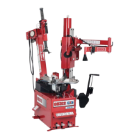
AC. After loosening and lubricating both beads, rotate
the table top until the clamps are in the 12, 3, 6, and 9
o’clock positions (figure 32).
AD. Clamp wheel from the outside. Position rim edge
into clamp at 12 o’clock position. Lower the wheel and
depress the clamp control pedal. Slowly move the
clamps inward until they securely contact the outside
edge of the rim.
TIP: This is usually accomplished by crouching down
in front of the tire changer, holding the wheel with the
right hand, and operating the clamp control pedal with
the left hand. This allows the operator to watch the
clamps as they move to ensure proper, damage-free
clamping.
4. Clamp wheel to the table top as described in item
AD. Always clamp custom wheels from the outside.
Figure 32 - Rotate Table Top to 12 o’clock
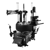
5. Depress the tire sidewall downward with the aid
of the robo foot providing clearance for the duckhead
®
to be positioned (figure 33). Move swing arm into
place. Increase the horizontal distance between the
demount head and the wheel an additional 1/16 to 1/8
inch with the adjustment knob.
Figure 33 - Helper Foot Depressing Sidewall of Tire
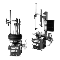
6. Lubricate upper bead liberally. Use the bead roller
tool to help push the tire bead down so bead area is
easier to reach for lubrication (figure 34).
Figure 34 - Lubricate Upper Bead
7. Locate the valve stem just before the demount
head before proceeding (figure 35).
Figure 35 - Position Valve Stem Under Demount Head
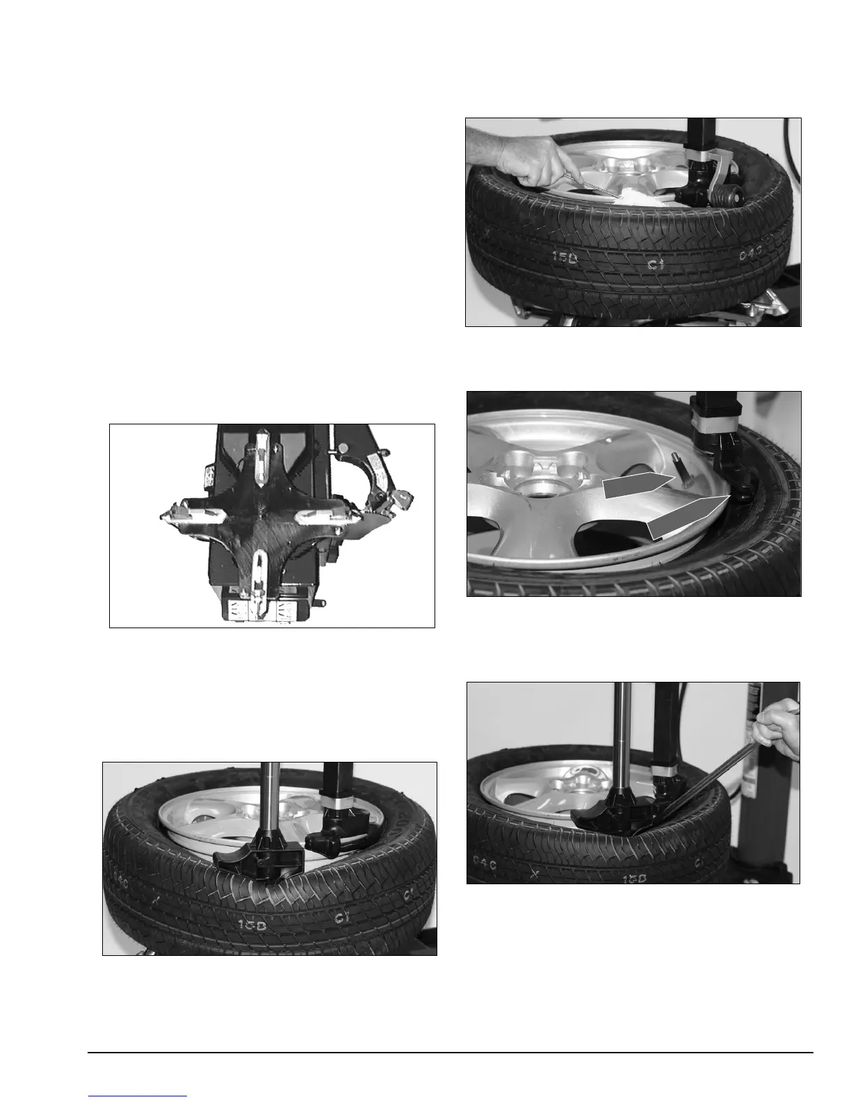
8. Insert the bead lifting tool between knob on
demount tool and tire bead (figure 36); use the helper
foot for extra clearance.
Figure 36 - Insert Bead Lifting Tool
Demount Head
Valve Stem
 Loading...