Installation
12
Connector
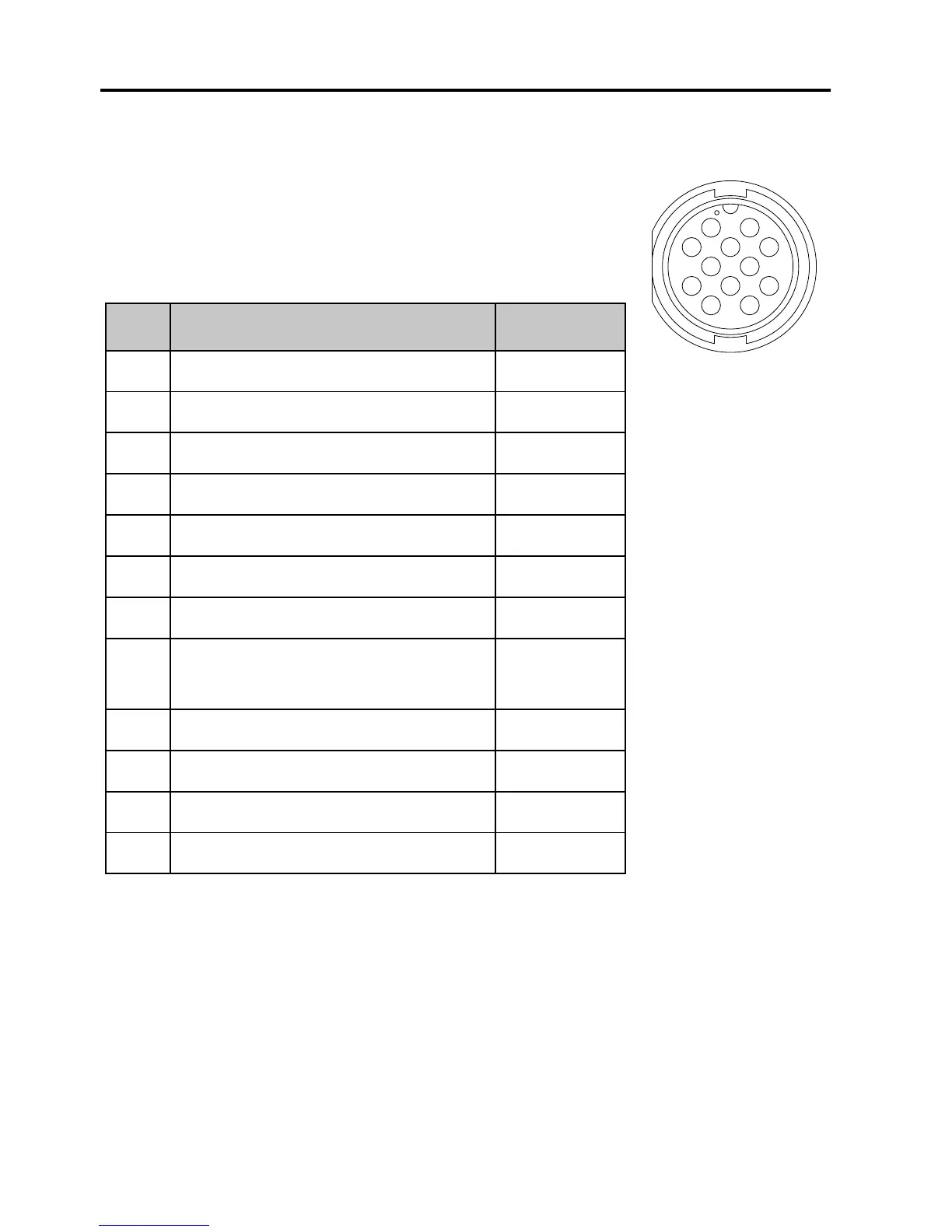
Connector type: Circular connector, 12 pin.
Pin assignment: Connector front view on the VHF
radio:
Connecting several Control Speaker Microphones
For instructions how to connect several Control Speaker Microphones
see the system configuration examples in the radio’s installation
manual.
Pin Description Wire color
1 GND for cable screen Brown
2 Internal GND=- Battery Blue
3 Battery supply when radio is on White
4 Battery supply when radio is on Green
5 CAN+ Yellow
6 CAN- Grey
7 Internal GND = - Battery Pink
8 On/off from Control Speaker
Microphone
Red
9 RX out + Black
10 RX out - Orange
11 TX in + Violet
12 TX in - Cyan
 Loading...