Do you have a question about the COBHAM Sea Tel 2400 and is the answer not in the manual?
Lists the Sea Tel products covered by the RED Directive 2014/53/EU.
Specifies the harmonized standards for EMC, SES, and Safety compliance.
Procedures for authorized technicians regarding ACU and ADE access.
Safety precaution against servicing equipment without assistance.
Importance of grounding for shock and lightning protection, cable routing.
Information on AC power connection to the ADE.
Warning against operating equipment in flammable environments.
Precautions for working with live electrical circuits.
Caution regarding internal lithium batteries and their replacement.
Overview of the stabilized antenna system's reliability and operation.
Explains the system's function for shipboard two-way satellite communications.
Details external inputs like Gyro Compass, GPS, phone, and fax.
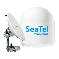
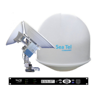
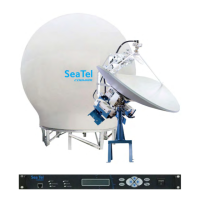
Outlines the two main groups: Above-Decks Equipment (ADE) and Below-Decks Equipment (BDE).
Describes setting up dual antennas for uninterrupted service due to blockage.
Explains configurations for accessing multiple networks via a dual network arbitrator.
Details the method for remotely reconfiguring the ACU for different beams or satellites.
Discusses standardized language for automatic beam switching via modem options files.
Addresses FCC requirements for continuous monitoring of pedestal pointing error.
Warns against direct internet connection and stresses changing default passwords.
Guidelines for choosing the optimal mounting location on a ship.
Importance of avoiding obstructions for signal integrity and preventing interference.
Considerations for selecting and preparing the mounting foundation.
Specific points to consider when mounting the Above-Decks Equipment.
Factors to consider when determining the height and design of the support pedestal.
Guidance on selecting mounting height and location to prevent vibration issues.
Discusses different mast types and considerations for mounting the ADE.
Details on vertical mast design and mounting considerations.
Discusses raked mast configurations and associated mounting challenges.
Explains girder mast designs and their stiffness characteristics.
Information on truss mast designs and guidelines for antenna mounting.
Requirements for providing safe access for installation and maintenance.
Guidance on selecting suitable locations for below-decks equipment.
General recommendations for cable installation and routing.
Specifics on coax cable selection and installation for ADE/BDE.
Guidelines for installing the antenna power cable.
Recommendations for the AC power cable for the air conditioner.
Notes on AC power for the Antenna Control Unit.
Guidance on selecting and installing the gyro compass interface cable.
References installation chapter for grounding information.
Important safety and tightening torque specifications for installation.
Steps to take before beginning the installation procedure.
Instructions for separating the base frame and radome crates.
Process for assembling the main Above Decks Equipment.
Procedure for opening and preparing the base frame crate.
Steps for installing the internal marine air conditioner unit.
Details on hardware kits and assembly for the pedestal and reflector.
Instructions for opening the radome crate to access panels and hardware.
Procedure for assembling the lower half of the radome panels.
Steps to sub-assemble the upper radome panels.
Procedure for closing the 144-inch radome assembly.
Steps for preparing the Above Decks Equipment for hoisting.
Instructions for installing the complete Above Decks Equipment.
Procedure for safely hoisting the Above Decks Equipment.
Steps for connecting the Above Decks Equipment to power and data.
Instructions for installing and connecting the Below Decks Equipment.
Safety and authorization warnings for installing system components.
Instructions for connecting AC power to the Below Decks Equipment.
Details on connecting various devices to the MXP.
Connection details for Out of Band Management equipment.
Interface connections for SBS or Synchro Gyro Compass.
Auxiliary wired RS-232 connection details.
NMEA 0183 I/O connections for Gyro/GPS Compass.
Auxiliary RS-232 connection details for Antenna M&C.
NMEA 2000 interface port details (future development).
Connecting other equipment as shown in the system block diagram.
Performing visual and electrical inspection of connections.
Performing visual inspection of work to ensure proper connections.
Emphasizes double-checking all wiring for safety.
Steps for setting up, calibrating, and commissioning the antenna system via MXP.
Reiterates caution about network security and default passwords.
Selecting the correct gyro compass interface signal type.
Procedure for operating the system without gyro compass input.
Calculating and entering the IF tracking frequency for the MXP.
Using SAT SKEW to optimize feed polarization for satellite signal.
Mapping zones to inhibit transmission due to blockage or RF hazards.
Step-by-step guide for programming blockage zones using MXP software.
Overview of configuring the satellite modem via the Communication Interface.
Selecting the reflector (Primary/Secondary) for modem configuration.
Defining the satellite modem manufacturer for system integration.
Specifying the communication interface type between MXP and modem.
Manually defining driver, detector, and positive satellite ID settings for custom modems.
Setting the 12VDC Pull Up resistor for positive satellite ID input.
Defining the logic level for mute signals from MXP to modem.
Setting the 12VDC Pull Up resistor for blockage output.
A table summarizing common modem lock and mute settings for various types.
Automatically calculates and sets Azimuth/Elevation trim offsets for antenna calibration.
Step-by-step process for manually optimizing antenna targeting.
Defines different patterns for satellite acquisition when signal is lost.
Selecting the transmit polarity for C-Band or Ku-Band feeds.
Controlling band selection for Ku-Band LNBs.
Selecting X-Pol or Co-Pol for Ku-Band linear feeds.
Steps to choose or create a satellite configuration.
Describes automatic satellite acquisition and operation when signal is found.
Troubleshooting steps when the system fails to find a satellite.
Troubleshooting steps when signal is found but modem lock is absent.
Procedure to select and target a different satellite.
Procedure for arranging cross-pol isolation testing with the NOC.
Reiterates caution about network security and default passwords.
Diagnosing and resolving issues with the ship's gyro compass input.
Details on the Sea Tel limited warranty for parts and labor.
Specifications for tightening torque values and Loctite product numbers.
Procedures for general maintenance tasks.
Steps for installing the selectable feed assembly on the reflector.
Using graphs to monitor motor drive torque and verify antenna balance.
Procedure for installing stow restraints to secure the antenna during underway conditions.
Technical specifications for the Above Decks Equipment (ADE).
Technical specifications for the Below Decks Equipment (BDE).
Compliance with various international standards and regulations.
Specifications for various cables used in the system.
Recommended coax cable types and sizes for L-Band.
Recommended wire gauges for AC & DC multi-conductor cables.
Specifications for the shielded gyro compass interface cable.
Power requirements and specifications for AC power cables.
Power requirements for the optional marine air conditioner.