EasyManua.ls Logo

COBHAM Sea Tel 6011-4 User Manual

COBHAM Sea Tel 6011-4
143 pages
To Next Page IconTo Next Page
Page #1 background imageLoading...
Page #1 background image
EAR Controlled - ECCN EAR99
This technical data is subject to US Government export control in accordance with the
Export Administration Regulations. Export of this data to any foreign country, or disclosure
of this data to a Non-US person, may be a violation of Federal law.
Sea Tel, Inc.
(trading as Cobham SATCOM)
4030 Nelson Avenue
Concord, CA 94520
Tel: +1 (925) 798-7979
Fax: +1 (925) 798-7986
Thrane & Thrane A/S
(trading as Cobham SATCOM)
Lundtoftegaardsvej 93 D, 2800 Kgs.
Lyngby, Denmark
Tel: +45 3955 8800
Fax: +45 3955 8888
Web: http://www.cobham.com/satcom
Email:
satcom.ohc@cobham.com
August 31, 2018 Document. No. 99-133136-A
EAR Controlled - ECCN EAR99
Sea Tel
6011-4 C/Ku-Band TVRO Satellite Antenna
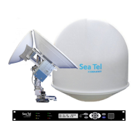
Installation Manual

Table of Contents

Questions and Answers:

COBHAM Sea Tel 6011-4 Specifications

General IconGeneral
Frequency BandC-Band, Ku-Band
Stabilization3-axis
TypeStabilized Antenna
Antenna Diameter1.5 meters
TrackingAutomatic
Reflector Size1.5 m
PolarizationLinear
Tracking Accuracy0.2 degrees RMS
Frequency Range10.7 - 12.75 GHz
Diameter1.0 meter
Mount TypePedestal
Antenna TypeParabolic
CompatibilityCompatible with most VSAT systems

Summary

Safety Precautions

Service Guidelines

Guidelines for user access, inspection, and maintenance by authorized personnel.

Service Alone Warning

Emphasizes the need for a second person during service and adjustments.

Grounding and Cable Safety

Precautions for grounding, cable routing, and shielding to prevent hazards.

Power Supply Guidelines

Specifies AC power connection requirements for the ADE.

Explosive Atmosphere Warning

Warning against operating equipment in the presence of flammable gases or fumes.

Live Circuit Precautions

Instructions on handling live circuits and avoiding electrical hazards.

6011-4 System Configuration

System Cables Overview

Discusses AC power and coaxial cables, referring to other chapters for details.

Other System Inputs

Mentions multi-conductor cables from Gyro Compass and computer.

System Block Diagram

Provides a high-level overview of the system components and their interconnections.

Site Survey - Shipboard

Site Selection Aboard The Ship

Criteria for choosing the best location for mounting the antenna and BDE on a ship.

Antenna Shadowing and RF Interference

Discusses how obstructions and interference can affect signal quality and antenna placement.

Mounting Foundation Requirements

Details requirements for the pedestal, its sizing, and its connection to the ship.

Mounting Height Considerations

Explains the impact of mounting height on tangential acceleration and antenna performance.

Mast Configurations

Discusses recommendations for mounting on ship masts and different mast types.

Safe Access to the ADE

Covers requirements for providing safe access to the Above Decks Equipment for servicing.

Below Decks Equipment Location

Discusses proper placement and rack mounting for below-decks equipment.

Cable Installation Guidelines

General guidance on cable routing, protection, and installation practices.

Grounding Procedures

Details grounding procedures for the ADE and its mounting to the ship's hull.

Installation Procedures

Unpacking and Inspection

Instructions for carefully unpacking and inspecting the equipment for damage.

Assembly Notes and Warnings

General notes on assembly, thread-locking, and torque values for fasteners.

Installing the ADE

Step-by-step guide for installing the Above Decks Equipment, including radome access.

Grounding the Pedestal

Procedures for grounding the antenna pedestal to the ship's hull for electrical safety.

Remove Shipping/Stow Restraints

Critical step to remove shipping restraints before energizing the antenna.

Cable Installation

General guidelines for shipboard cable installation, avoiding damage and ensuring routing.

Installing Below Decks Equipment

Instructions for installing the ACU, Terminal Mounting Strip, and other BDE components.

Connecting Below Decks Equipment

Guides the connection of BDE components as per the system block diagram.

Final Checks

Performs visual and electrical inspections to ensure correct connections.

Power-Up Procedure

Procedures for powering up the ACU and antenna system after installation.

Antenna Maintenance

Covers routine maintenance procedures for the antenna system.

Basic Setup of the ACU

Operator Settings

Setting ship information and satellite details for system operation.

Setup Parameter Display

Accessing and navigating system setup parameters, with cautions on changes.

Default Setup Parameters

Lists factory default parameters for the ACU and PCU, noting optimization needs.

Save New Parameters

Procedure for saving changed parameters into NVRAM for permanent storage.

Setup - Dual Reflectors

Optimizing C-Band Targeting

Detailed steps for optimizing the C-Band reflector's targeting and settings.

Optimizing Ku-Band Targeting

Detailed steps for optimizing the Ku-Band reflector's targeting and settings.

Setup - Ships Gyro Compass

Gyro Type Selection

Selecting the correct GYRO TYPE parameter for the ship's gyro compass interface.

Updating GYRO TYPE Parameter

Manual procedure for updating the GYRO TYPE parameter and saving changes.

Operation Without Gyro Compass

Recommendations for operation without a gyro compass, including alternative solutions.

Setup - Tracking Receiver

IF Tracking Frequency

Calculating and entering the IF tracking frequency for satellite signal acquisition.

KHz Frequency Setting

Setting the KHz rate for the tracking frequency in the ACU.

FEC Setting

Setting the Forward Error Correction rate, specifically for L-Band SCPC Receivers.

Tone Usage

Discusses the use of the 22 KHz tone for band selection in TVRO applications.

Volt Setting

Selecting receiver voltage for proper port selection based on satellite polarization.

SKEW Adjustment

Optimizing polarization for linear feeds and setting Skew to 0000 for circular feeds.

NID Setting

Setting the Network ID (NID) parameter, typically to 0000.

Setup - Band & Reflector Select

Band and Reflector Selection

How to set band selection for C-Band (REFL A) and Ku-Band (REFL B) reflectors.

Setup - Targeting

QOR Dual Reflector Targeting

Procedure for optimizing targeting for both C-Band and Ku-Band reflectors.

AUTO TRIM Function

Automatic calculation and setting of Azimuth/Elevation trim offsets for antenna calibration.

Manually Optimizing Targeting

Manual procedure for optimizing targeting by recording calculated and peak positions.

EL TRIM Adjustment

Adjusting the Elevation trim offset to correct alignment errors or imbalances.

AZ TRIM Adjustment

Adjusting the Azimuth trim offset to compensate for installation alignment errors.

Setup - Home Flag Offset

Electronic Calibration of Relative Antenna Position

Procedure to electronically calibrate the antenna's relative azimuth position using HFO.

Mechanical Calibration of Relative Antenna Position

Method for mechanically calibrating the relative antenna position using the home flag sensor.

Setup - Searching

Searching Operation Overview

Overview of the ACU's search pattern initiation and termination criteria.

Changing Search Parameters

Explains how to modify various search pattern parameters.

Save New Search Parameters

Saving modified search parameters into NVRAM.

Setup - Blockage & RF Hazard Zones

Blockage Mapping (AZ LIMIT Parameters)

Programming relative azimuth sectors (zones) for blockage or RF hazard areas.

Save Blockage Parameters

Saving programmed blockage zones and RF hazard parameters into NVRAM.

Setup - Other Parameters

Setup Parameter Display

How to access and navigate the system setup menus, with cautions.

5V OFFSET Setting

Setting the CCW 5v Polang servo position reference.

5V SCALE Setting

Setting the 5V Polang servo motion scale factor.

REMOTE COMMAND Parameter

Parameter for issuing diagnostic commands to the PCU.

REMOTE MONITOR Parameter

Parameter used to monitor diagnostic command results.

Disable/Enable DishScan®

Procedure to disable or enable DishScan for specific tests or diagnostics.

Satellite Reference Mode

Managing satellite reference mode to improve tracking accuracy with gyro or without.

Saving Remote Parameters

Saving changed remote parameters to NVRAM.

Stowing the Antenna

Installing Stow Restraints

Instructions for installing stow restraints to secure the antenna during ship movement.

Remove Shipping/Stow Restraints

Instructions to remove shipping restraints before powering up.

Operation Procedures

Target a C-Band Satellite

Procedure for targeting and acquiring a C-Band satellite.

Target C-Band to C-Band Satellite

Steps to switch tracking from one C-Band satellite to another.

Target C-Band to Ku-Band Satellite

Steps to switch tracking from a C-Band to a Ku-Band satellite.

Target Ku-Band to Ku-Band Satellite

Steps to switch tracking between Ku-Band satellites.

Functional Testing

ACU / Antenna System Check

Initial check of the ACU and antenna system after power-up and reset.

Latitude/Longitude Update Check

Verifying that the integrated GPS is updating positional information correctly.

Heading Following Test

Checking if the ACU's heading display accurately follows the ship's gyro compass.

Blockage Simulation Test

Testing the blockage output function by simulating a blocked condition.

Four Quadrant Tracking Test

Testing the antenna's tracking accuracy across all four quadrants of signal level.

Installation Troubleshooting

Warranty Information

Details the Sea Tel Limited Warranty coverage for parts and labor.

Troubleshooting the ACU

Common problems encountered with the ACU and initial steps to resolve them.

Troubleshooting Gyro Compass

Addresses issues where the heading display doesn't follow movement or reports errors.

Maintenance Procedures

C-Band Feed Polarity Selection

How to select or reverse polarity for C-Band LNBs using the polarity select knob.

Replacing Ku-Band LNB

Instructions for installing and aligning replacement Ku-Band LNBs.

Optimizing Ku-Band Polarization

Procedure to optimize linear polarization based on received signal level using SKEW.

Bluetooth Installation & Operation

Bluetooth Prerequisites

Minimum requirements for using the Bluetooth device feature.

Installing ADE Bluetooth Hardware

Steps to install the Bluetooth hardware for the Above Decks Equipment.

Installing BDE Bluetooth Hardware

Steps to install the Bluetooth hardware for the Below Decks Equipment.

Diagnostic Mode

Instructions for using diagnostic modes, noting when to refer to other sections.

Removing ADE Bluetooth Hardware

Steps to remove the Bluetooth hardware from the ADE.

Removing BDE Bluetooth Hardware

Steps to remove the Bluetooth hardware from the BDE.

Software Installation via Bluetooth

Updating PCU or DAC software using the Bluetooth connection.

Normal Operation Mode

Steps to return to normal operation after Bluetooth setup or removal.

6011-4 TVRO Technical Specifications

Stabilized Antenna Pedestal Assembly

Technical specifications for the stabilized antenna pedestal, including motors and sensors.

QOR Dual Reflector Configuration

Configuration details for the QOR Dual Reflector system, including C-Band and Ku-Band assemblies.

Interchangeable LNB Options

Details various interchangeable LNB options available for the system.

MK 2 Pedestal Control Unit (PCU)

Specifications and connectors for the MK 2 Pedestal Control Unit.

MK 2 Motor Driver Enclosure (MDE)

Specifications and connectors for the MK 2 Motor Driver Enclosure.

400 MHz Modems

Specifications for the 400 MHz modems used in the system.

76” Radome Assembly

Specifications for the 76” radome assembly, including size, material, and wind resistance.

ADE Pedestal Power Requirements

Power requirements for the ADE pedestal, including AC input and consumption.

Environmental Specifications

Environmental operating conditions, including climatic and transit specifications.

Below Decks Equipment

Lists below-decks equipment like ACU, TMS, Satellite Receiver, and Multiswitch.

Cable Specifications

Details specifications for antenna control and IF coax cables.

DRAWINGS

6011-4 Model Specific Drawings

Lists specific drawings related to the 6011-4 model for diagnostic reference.

Radome Strain Relief Installation Procedure

Procedure Purpose

Defines the purpose of the procedure for installing strain reliefs in smooth base radomes.

Procedure Scope

Outlines the applicability of the procedure to various radome sizes and mounting patterns.

Tools and Materials

Lists necessary tools and materials for performing the radome strain relief installation.

Installer Responsibilities

States the installer's responsibility to observe safety precautions during the procedure.

Installation Procedure Steps

The main procedural steps for installing radome strain reliefs, starting with removing the cable pass-through.

Making Holes for Strain Reliefs

Planning and making the necessary holes for strain reliefs, with spacing guidelines.

Drilling Pilot Holes

Detailed steps for measuring, marking, and drilling pilot holes for strain reliefs.

Using Hole Saw

Using a hole saw from the outside to create holes, with precautions to avoid damage.

Cleaning Hole Edges

Cleaning the edges of drilled holes with a file.

Test Fitting Strain Reliefs

Testing the fit of strain reliefs and making adjustments.

Sealing Hole Edges

Sealing cut edges with fiberglass resin to preserve radome strength.

Refer to Strain Relief Drawing

Reference to the strain relief assembly drawing for installation.

Rotate General Assembly (G.A.)

Rotating the General Assembly to ensure proper cable routing and no interference.

Strain Relief Positioning (80-180cm Radomes)

Positioning guidelines for strain reliefs on smooth based radomes.

Strain Relief Positioning (76-inch Radomes)

Positioning guidelines for strain reliefs on 76-inch radomes.

Related product manuals